1999 GMC k2500 7.4l build detail

  • HTML tutorial

ThundahBeagle

Rank V

Advocate I

1,548
Massachusetts
First Name
Andrew
Last Name
Beagle
Member #

0

2017
We bought a shipping container for the cabin.
Here's a nice pic of my view while sipping coffee in the morning before we set out to prep for the delivery.
View attachment 291546

Here's my partner limbing some of the trees to make room for the container delivery.

View attachment 291535
I have had TWO. 2-door models of this. The little ones always loved climbing all over it and getting on the roof. Never once did I worry about dents in the roof, nor did I see any significant damage from them.

My 2014?! No way, kids. Stay off the roof!
 
  • Love
Reactions: kunstmilch

ThundahBeagle

Rank V

Advocate I

1,548
Massachusetts
First Name
Andrew
Last Name
Beagle
Member #

0

Then, In November of 2022, tragedy struck the family.

My sister who was a VA Nurse had just moved to the cabin and began work to transform the VA hospital in the area after building out a great program in San Diego. Was hit head on by a semi truck that swerved into her at the last possible second. It was like her third day of work or something like that...I found out days later when I received a call from a neighbor, they found out she was in ICU. Alive but barely. I had to go up and take care of the situation, which isn't great cause Im disabled myself...the blind leading the blind. She survived, but is now permanently disabled, lost her job, basically lost everything. It sucks.
View attachment 291669
View attachment 291671
Angels and ministers of Grace protect her.
 

OG_Zuninja

Rank I

Enthusiast I

201
Virginia Beach, VA, USA
First Name
Jon
Last Name
Zuninja
Then, In November of 2022, tragedy struck the family.

My sister who was a VA Nurse had just moved to the cabin and began work to transform the VA hospital in the area after building out a great program in San Diego. Was hit head on by a semi truck that swerved into her at the last possible second. It was like her third day of work or something like that...I found out days later when I received a call from a neighbor, they found out she was in ICU. Alive but barely. I had to go up and take care of the situation, which isn't great cause Im disabled myself...the blind leading the blind. She survived, but is now permanently disabled, lost her job, basically lost everything. It sucks.
View attachment 291669
View attachment 291671
Holy shit! It's a miracle she survived that at all. That's some serious carnage!
 
  • Like
Reactions: kunstmilch

kunstmilch

Rank V
Member

Advocate II

1,597
Pomona, CA, USA
First Name
Erich
Last Name
Wise
Member #

29953

Ham/GMRS Callsign
GMRS call sign: WRFL229
ok, so where was I...

2023
Unfortunately the suspension that was put in (which was good) needed maintenance (duh) but the guys at Reynolds assured me everything was sealed since it was a new system...well, it wasn't. and they hadn't greases the fittings when I brought it in...I also hadn't greased the fittings, since I was told not to. hmm. well by this point the suspension was metal on metal and obviously so...went down and looked around, and well...since im here...

Here is some old "cake" from some old leaks that never got cleaned up...
IMG_2529.jpeg

and here's some rust that developed after that last winter...no rust before, so I will need to address this before it possibly gets worse...it's very minor surface rust now...but traveling in winter where salt gets used is no good.
IMG_2531.jpeg
IMG_2532.jpeg
well the
re also seems to be wires that were never routed or protected properly...

IMG_2541.jpeg
took a horoscope to check the tunnel of the frame...most of the truck is "c" channel but there a section from the front to about middle of foot doors that is box. Honestly it looks better than I thought it would.
Image_2023-07-26 09_11_32_273.JPGImage_2023-07-26 09_13_27_739.JPGImage_2023-07-26 09_11_45_915.JPGImage_2023-07-26 09_14_53_015.JPGImage_2023-07-26 09_19_25_324.JPG
Saw multiple YouTube videos and read some articles...you know, research, lol. Mostly it was Toyota box frames rotting out, but a lot of good problem solving on how to clean em up. here's some more goo...I spent a lot of time and used a lot of products to clean up all the old grease...tried steam, super clean, detergent pods, fabulouso, simple green, brake cleaner (both kinds), etc... the thing that I found worked best of all, citrol. Citrol was by far and away the best thing I used.
IMG_2617.jpeg

IMG_2620.jpeg
IMG_2632.jpeg
IMG_2633.jpeg
IMG_2638.jpeg
while I'm here...the park lights that I replaced with LED amber were now garbage. ugh. but also the connections were caked.
IMG_2642.jpeg
IMG_2645.jpeg
Used a sewer line cleaner tip that spins to flush out and clean the boxed part of the frame, after blasting it with lots of detergent. Then will spray in some Mastercoat metal prep and rust remover.
IMG_2657.jpeg
ok...switching gears a bit...replaced some seam sealer around the "b" pillars as it wasn't holding up anymore. Bought the GM product.
IMG_2665.jpeg
 

kunstmilch

Rank V
Member

Advocate II

1,597
Pomona, CA, USA
First Name
Erich
Last Name
Wise
Member #

29953

Ham/GMRS Callsign
GMRS call sign: WRFL229
2023

Addressing sound and heat. Luckily for me theres a lot of good science on these topics. There is also a lot of misunderstanding on the internet it turns out. People seem to be pretty passionate about this as well. I think it's because so much is at stake and it becomes an ideology. For me, I am doing the best I can...mistakes will be made. I enjoy the research and the process. Honestly, being disabled mean I spend way too much time in bed unable to do the things I want...so I dont mind taking it slow and getting it done "right"
Also, science being science...our understandings change with experiments and experience. Here is what I've come up with.

For sound, we need to address mechanical vibrations and airborne sound, which is compressive forces on air. The higher the Hz (pitch) the easier to deal with as these are shorter waves and less "deep" than lower octaves. Having a V8 doesn't help. Having big treaded tires doesn't help. having large metal panels doesn't help. US submarines need to be silent, for I hope obvious reasons. All politics aside, there's a lot of science that has been developed to deal with sound and vibrations. One of the most effective systems (and all of these things should be thought of as systems) is the use of constrained layers. Think of it like a sandwich of two ridged layers with a forgiving middle layer. Now I am way oversimplifying all this of course, but if you are looking for quiet...the system I've implemented works pretty well. Unfortunately it adds weight. Compromise is everywhere.

I have already shown some of the work done and for convenience will just list it here.
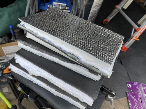
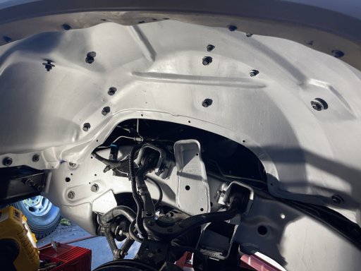
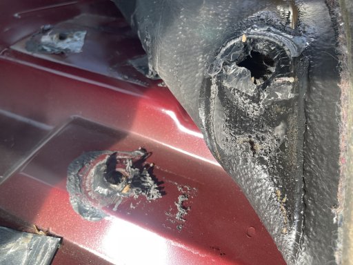
1. constrained layer, or dampening mats for mechanical vibration, made from butyl and aluminum sheet, the butyl sticks to the metal panel and created the constrained layer, the thicker the aluminum sheet the better.
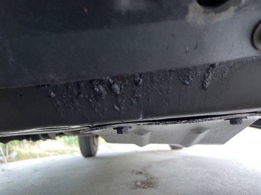
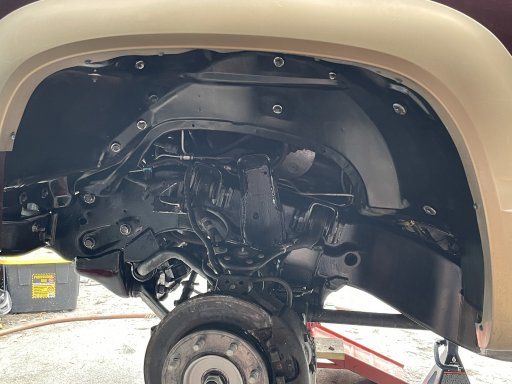
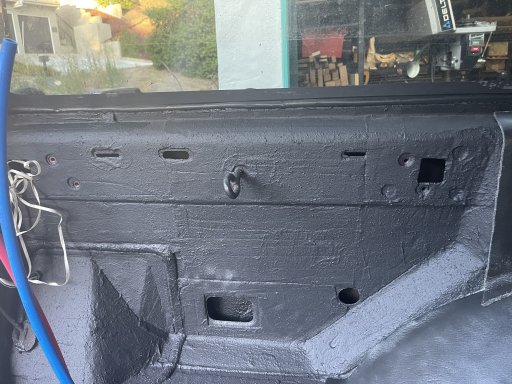
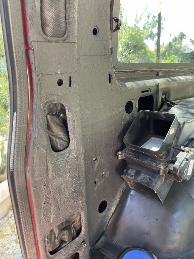
2. Viscoelastic, layer this on top as overkill for the dampening of mechanical vibrations. The product used includes anti corrosive agents and pretty effectively seals the area from water and oxygen intrusion as well. This layer adds some mass, but mostly absorbs vibrations and releases that energy as tiny amounts of heat.
3. closed cell foam glued to mass loaded vinyl. Not shown yet, still a ways away from that step...this layer is the layer that does what everyone seems to think the constrained layer does. This layer effectively addresses airborne waves. The foam blocks many of the higher frequencies and the mass loaded vinyl that is attached addresses lower waves. Because the foam is a forgiving layer and the vinyl less so, it acts as another constrained layer, allowing the vinyl to move and absorb most of the frequencies. Added benefit of the foam is thermal effective barrier as well. With this layer, you really want 100% coverage, overlapping here is a good idea, and aluminum tape for any seams...this isn't the layer to skimp on.

For thermal insulation, there is also a lot of good science (hey wha'd'ya know?!) There are three main things to address here (which bring up other issues). Heat can be classified into two main types: sensible heat, which can be felt and measured, and latent heat, which is absorbed or released during a change of state, such as melting or vaporization (think here also of heat soak). Additionally, heat transfer occurs through three mechanisms: conduction, convection, and radiation. We need to address these in ways that are effective.

To address these in my vehicle, I chose the following systems.
1. 1/4" closed cell flame retardant vehicle foam. This addresses direct conduction and stops thermal bridging. I am not particularly happy to use foams but this is the best I found for what I need to address, the other bonus is again sound absorption. (this also effectively acts as a vapor barrier, we can get into that later)
2. 3M SM600L Thinsulate (Compromises: I don't believe 3M when they say this is neutral to health, and I dont like 3M politics, but their products are too effective to ignore here. ) This was designed for acoustic insulation, so added bonus, but has been found to be very effective for stopping convection. I had been thinking of using mineral wool, and do use it in a couple small spots, but this is a better fit for our needs.
3. aluminized foam as the radiant barrier, not the bubble wrap "reflectix" but the same idea at least. This layer, more than the others really depends on proper installation for effectiveness, a lot of people using it and getting minimal effective value. For our use, we have this layer glued to the thinsulate, which acts as a 4" air gap. Both sides are aluminized.

This system isn't static either, it changes around the vehicle dependent on how that location needs to be addressed.

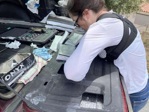
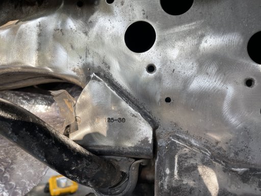
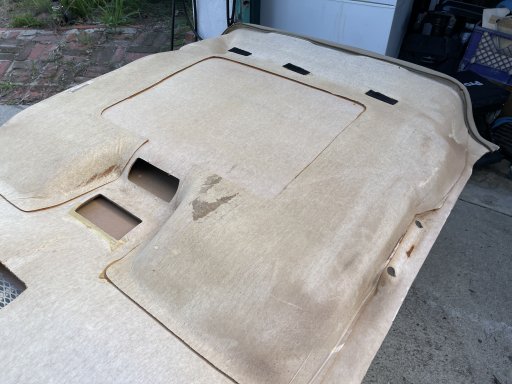
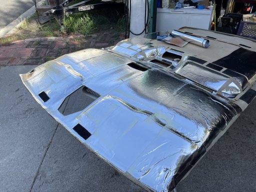
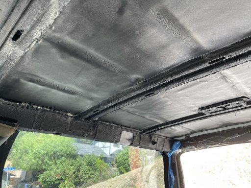
Here is how we addressed the tailgate...not an easy one.

IMG_2670.jpeg
IMG_2680.jpeg
IMG_2681.jpeg
 

kunstmilch

Rank V
Member

Advocate II

1,597
Pomona, CA, USA
First Name
Erich
Last Name
Wise
Member #

29953

Ham/GMRS Callsign
GMRS call sign: WRFL229
2023
More cleaning and finding issues...yikes...
IMG_2683.jpeg
IMG_2684.jpeg
IMG_2692.jpeg
IMG_2727.jpeg
Cleaned and added Metal prep and rust remover. Adds a thin layer of zinc.
IMG_2731.jpeg
IMG_2732.jpeg


After adding 2 Coates master coat primer.
IMG_2742.jpeg
After adding 2 coates AG111 satin black.
IMG_2760.jpeg
Here are some more process photos, hope they might be helpful.
IMG_2765.jpegIMG_2769.jpeg
IMG_2772.jpeg
IMG_2780.jpeg
IMG_2783.jpeg
 

Attachments

kunstmilch

Rank V
Member

Advocate II

1,597
Pomona, CA, USA
First Name
Erich
Last Name
Wise
Member #

29953

Ham/GMRS Callsign
GMRS call sign: WRFL229
Roughly same timeframe 2023

Bought a new grill...can you spot the immediate problem? These aftermarket grills are not as robust as the OEM and not as robust as the older aftermarket ones either so Ive heard. If I'm going to go through the bother of plastic welding and fixing this I might as well do it with the original. Had to send it back. (did this twice, same area was broken, the second one had evidence of a previous fix.)
IMG_2798.jpeg
IMG_2799.jpeg

Back to the interior...
time to pay some attention to the ceiling panels. Not bad for a car thats old enough to drink.
IMG_3022.jpeg
IMG_3040.jpeg
Easiest method was to apply a layer of non perforated reflective barrier directly on the underside. then the thinsulate can go between this and the ceiling. Wherever theres a gap it will help. I am not using this stuff as a vapor barrier fyi.
IMG_3055.jpeg
 

kunstmilch

Rank V
Member

Advocate II

1,597
Pomona, CA, USA
First Name
Erich
Last Name
Wise
Member #

29953

Ham/GMRS Callsign
GMRS call sign: WRFL229
2023
The Variable Speed Controller for the Flex-A-Lite fans died. Opened it all up and now I'll be addressing all of this wiring, ugh. While im here...
IMG_3059.jpeg
IMG_3062.jpeg
Green wire goes to the A/C Compressor for signal override. Under this tape? Another t-tap.
IMG_3065.jpeg
traced the ignition signal wire...fuse taps. No, they aren't as bad as t-taps. But I dont like it. Now I'm going to open up a can of worms (again) to figure out how to do this better... One of the indues is that with the taps in place here the lid doesnt properly close and one of the clips snapped. I starter with buying replacement cover and body and was going to just put everything back in a new casing...but it turned out to not be that easy...For one, the Maxi fuses are in on the powered side with a bus rail of Delphi 800 terminals that aren't made anymore, and best I could find I'd have to order 1,000...um, no.
IMG_3070.jpeg
Also bought another VSC for the fans...Turns out it is best to have the VSC on connectors that you unplug anytime you jumpstart the car or anything like that...that's fairly annoying, I think I need to put some kind of diode to keep spikes out of the circuit. I had a hell of a time with finding a connector that could easily handle 0amps but was sealed...I am thinking of changing this Anderson SB50 to an MP630 but this is what I came up with at the time. If you look you can also see I messed up the label here and the Batt neg also says B+
IMG_3072.jpeg
 

kunstmilch

Rank V
Member

Advocate II

1,597
Pomona, CA, USA
First Name
Erich
Last Name
Wise
Member #

29953

Ham/GMRS Callsign
GMRS call sign: WRFL229
Once I started looking, I just kept finding things I didnt like and needed to address. And to think it all started cause I put some grease in my ball joints.
IMG_3150.jpeg
IMG_3154.jpeg
pressure switch for air compressor, floating.

IMG_3092.jpeg
Need to move the welder to make room for the second battery.
IMG_3118.jpeg
This is how the original tow package was installed through the firewall. I mean it worked...but I'll be addressing that too.
IMG_3205.jpeg
And then there is the starter...this is what made me decide to take a close look at everything and end up tearing a lot out and redoing it. hard to tell with the char here, but it had melted down to the wire in one spot. Nope. Don't like that.
IMG_8776.jpeg
 

Attachments

kunstmilch

Rank V
Member

Advocate II

1,597
Pomona, CA, USA
First Name
Erich
Last Name
Wise
Member #

29953

Ham/GMRS Callsign
GMRS call sign: WRFL229
2024

Here you can see the inside of the traditional electrical center used by GM in the 90's. After 20 some aught years the insulation has some damage due to vibration and here also you can see the large bus rail for the maxi fuses. Each rail has 4 terminals and there are two for the electrical center. There are three other busses total. they are in the middle area with the ATM fuses. Two tough the maxi rail, and one is an ignition bus. Left side is the relay wires.
IMG_8862.jpeg
IMG_8860.jpeg
 

kunstmilch

Rank V
Member

Advocate II

1,597
Pomona, CA, USA
First Name
Erich
Last Name
Wise
Member #

29953

Ham/GMRS Callsign
GMRS call sign: WRFL229
2024

Here is the t-tap that had been installed for the VSC's A/C signal.
IMG_3501.jpeg


To address the t-tap on the A/C signal wire, I used a metri-pak bus and used that to house the A/C diode as well D104.
IMG_3810.jpeg
In this pic you can see the old diode housing still wired. It's a bit bulkier, but otherwise I am happy with this solution. Once all the wiring is done and the harnessing is in place I think it will make it easier for any maintenance and troubleshooting as well.
IMG_3874.jpeg
 

Attachments

kunstmilch

Rank V
Member

Advocate II

1,597
Pomona, CA, USA
First Name
Erich
Last Name
Wise
Member #

29953

Ham/GMRS Callsign
GMRS call sign: WRFL229
2024
Cleaning up the starter and making new wires for it.
IMG_3694.jpeg
IMG_3787.jpeg
The 4/0 welding wire is actually closer to 3/0. Ended up changing the lugs for a better fit.
IMG_3723.jpeg
IMG_3740.jpeg
internal layer of braid mostly cause it was already on the wire. Convoluted loom non-slit, gonna seal this up for this wire, It's EPDM and can degrade over time with oils. the translucent band is heat sensitive melt glue for extra sealing around the ribs. It would have been less bulky with a thinner loom, but this was the smallest that fit.
IMG_3727.jpeg
This is before I changed the lug, but after I applied the heat shrink to the loom and wire.
IMG_3729.jpeg
Here you can see the fit of the 3/0 lug. Also the fiberglass heat loom.
IMG_3746.jpeg
IMG_3748.jpeg
Closing it all in and making it one unit.

IMG_3763.jpeg
Labeling and cover.
IMG_3782.jpeg
The purple signal wire was replaced too. This time with 10awg SRML (Silicone Rubber Motor Lead) This has type K wire like anchor and is tinned, but uses a high temperature and chemically tough silicone with a fiberglass braid cover. Terminated with a Burndy Nylon lug. Then used purple polyolefin heat shrink and labeled.
IMG_3768.jpeg
IMG_3779.jpeg
 

Attachments

  • Like
Reactions: OG_Zuninja

kunstmilch

Rank V
Member

Advocate II

1,597
Pomona, CA, USA
First Name
Erich
Last Name
Wise
Member #

29953

Ham/GMRS Callsign
GMRS call sign: WRFL229
2024-25
I pulled the the lighting harness, making sire all the lighting works well...and figured it would be an easier harness to take apart and learn from as well. The harness runs from connector C102, by the firewall to the front of the truck then takes a right turn to the passenger side and back by the right side battery at ground G112. Here is what the technicians manual has for OE. It's white on black as I discovered looking at all this on screen with all the white hurt my eyes. My truck didnt come with the fog light option, and this is only a few of the schematics just for reference.
Screenshot 2025-04-23 at 10.43.31.png
Here is the circuit description. The harness however contains a lot of other shit along the way as we will discover.
Screenshot 2025-04-23 at 10.48.52.png
Here is some of the location descriptions.
Screenshot 2025-04-23 at 10.51.30.png
Up until pretty recently, it was very important to illustrate locations rather than take a picture, since it was often the case that photocopies were made and photo images degrade in photocopy much quicker and become harder to decipher than illustrations. Also, illustrations have clear decisions on how something is represented that can make something clearer, such as distorting line quality, or size of a component. I see in many of the newer manuals there are computer generated three dimensional "photos" that make for clear illustration. But I still think a good line drawing is hard to beat, of course having both is best. As an aside, when I went to school, our instruction was at the transition phase, so we learned both old school drafting and computer aided design. Both are useful, but more and more as long as you have access to a database the computer models blow the illustrations out the water. Here is the illustration of the OE Forward Lamps Harness.
Screenshot 2025-04-23 at 10.55.27.png
Something that was driving me crazy, was that I had a connector on this harness that I couldn't find a reference to...after a lot of digging into different systems I finally found a reference. In my particular truck, the references to C101 as a multi pin connector are incorrect. C101 gets used as a single pin red wire circuit 702. Here is the schematic that shows it. The Illustration is for some reason even harder to find.
Screenshot 2025-04-23 at 11.39.14.png
Screenshot 2025-04-23 at 11.51.21.png
This is the illustration that is the main reference to this area and the Forward Lamp Harness. You can see that the critical part I needed was omitted in the illustration.
Screenshot 2025-04-23 at 11.53.35.png
And here is the "offending" connector in the truck.
IMG_4143.jpeg
The harness after being pulled out.
IMG_4144.jpeg
Then on to the next issue to resolve...these light sockets are "LS7" if I remember correctly...they are no longer produced, and are upwards of $60-70 each. Ouch.
IMG_4175.jpeg
I thought perhaps I could open them up and replace the terminals. In this design, the terminals aren't sealed...there was a clay like substance used to fill and "seal" the area. The terminals are still available, but much like the Maxi rails, they are sold only in high quantities. No I dont need 10,000 units thank you. well, I bought a sample unit of the "W3 " socket from CustomConnectorKits (no affiliation) to see if that model will fit. It is a sealed unit and is still in production across a wide range of vehicles...as well the parts are all for more common. Sure enough it fits well. I will be using these as an "upgrade." no pics yet.

As for the harness...it included multiple factory splices in the harness. If you are as curious as I was to see what these look like, as well as how they held up over the years, here are some shots...
IMG_4186.jpeg
IMG_4188.jpegIMG_4189.jpeg
IMG_4191.jpeg
IMG_4193.jpeg
Here's one that didnt fair as well...
IMG_4195.jpeg
IMG_4247.jpeg
After cleaning and taping of the junction points and measuring everything out, triple checking connectors and circuit numbers, I began the work of figuring out how I was going to replace this all. I have a working document to help keep track of the new harness. Here is what it looks like ( it is a digital document with lots of "layers" but this should give a good idea)

Screenshot 2025-04-23 at 12.19.40.png
 

kunstmilch

Rank V
Member

Advocate II

1,597
Pomona, CA, USA
First Name
Erich
Last Name
Wise
Member #

29953

Ham/GMRS Callsign
GMRS call sign: WRFL229
Going into this I was learning GM's specific language in their schematics. It's not a consistent language exactly, the decisions seem to be made by teams of people. I wanted to use GM's language as much as possible so that the manual and schematics of my alterations aren't jarring when going back and forth. I know the language has also changed since then and is all done on a cad system so a lot of the elegance is lost, but efficiency is up. I'll show you what I mean.

This is where the term "star grounding" comes from, it's these drawings. There's a lot of information to take in on this page, and a whole lot of decisions made on how to present the circuit path so that our eyes and brains can, for lack of a better term, feel how it all works together.
Screenshot 2025-04-24 at 11.46.18.png

Here is another style that is also centering splice S259. One can see there are very different decisions on the layout. Both have elegant answers to the problem.
Screenshot 2025-04-24 at 11.53.24.png


Here one can see a very different type of elegance, one of efficient layout on a specific grid (you can kind of see how the two above move toward this)
This also features splice S259, and is designed also with screens in mind.
Screenshot 2025-04-24 at 12.00.18.png

So far I've show ground distribution schematics here. Power distribution, fuse block details, and individual system circuit schematics all have different layouts based on what information needs to be conveyed. For anyone who already knows all this, I hope this will save others who don't some time, also I am trying to leave out information that is unnecessary, anything I am getting wrong or might be useful to add I would greatly appreciate as I've just been figuring this out as I go along, my training isn't in automotive design in any way, I dont even consider myself a "car guy."

Here was my first "finished" attempt at a schematic for the Redarc Manager30 integrated into my system.
Screenshot 2025-04-24 at 11.39.37.png

Here is a later version of the same circuit after reviewing the GM technical manual drawings. This one was in progress when abandoned after I realized I was moving to a vertical format, but I think it conveys the difference and decision making process well.
Screenshot 2025-04-24 at 12.15.48.png


One of the benefits of laying these schematics out in detail is getting to really understand the circuits. As changes are made in the design, the circuits get updated in the drawings, and a lot of things get caught in this faze.

Here is one of the ground distribution schematics (sticking with ground distribution) I drew up a while back. Things have changed since then in the design, but I hope it conveys the idea. I am also hoping someone can tell me if theres something really wrong with the layout. It doesnt convey the "star" like I'd like, but after a bunch of iterations this is what I had ended up with when I was trying to stuff as much as I could in there.
Screenshot 2025-04-24 at 12.23.52.png
 

kunstmilch

Rank V
Member

Advocate II

1,597
Pomona, CA, USA
First Name
Erich
Last Name
Wise
Member #

29953

Ham/GMRS Callsign
GMRS call sign: WRFL229
From the technical manual:

The Power Distribution schematic shows the wiring from the Battery and Generator to the Starter Solenoid, Fuse Block, Ignition Switch and Light Switch. The first component after a Fusible Link is also shown. In certain instances, the first component after a Fuse Block fuse and Light Switch is also shown.

The Power Distribution schematic refers to Fuse Block Details or the appropriate section schematics. By using these schematics, power distribution wiring can be followed from the Battery and Generator to the first component after a Fusible Link, Fuse or Light Switch. The ability to follow the power distribution wiring to the first component in each circuit is extremely helpful in locating short circuits which cause fusible links and fuses to open.

So:
Battery and Generator
>
Starter Solenoid/Fuse Block/Light Switch
>
(sometimes) First component after Fuse Block fuse/Light Switch
>
Reference to Fuse Block Detail

In these drawings you can see this laid out. In this first one, the next page would be the Battery and Lighting fuses, then the IGN fuse, etc.
Screenshot 2025-04-24 at 12.45.49.png
Screenshot 2025-04-24 at 12.48.37.pngScreenshot 2025-04-24 at 12.49.40.png

Here was one of my versions of this first page, which dramatically changed due to circumstances.

Screenshot 2025-04-24 at 12.52.55.png

Here is the latest iteration, you can see things have changed here. For one, There is no longer a Redarc SBI12 in the circuit. I might bring in something similar for a winch provision, but Redarc was kind enough to exchange the BCDC50 with their new version they named the "Alpha" for some stupid reason, but nomenclature aside, the new version incorporated what I had asked them about in the first place and had been bothering them about and they offered, very graciously to have me pay the difference and exchange for the new one. This new one has a version of the jumpstart feature that renders the SBI12 redundant in this particular case. The main feature I wanted however was charging the starting battery with the BCDC.

The second thing of note, is there is no longer a power distribution block (formerly a Blu Sea Systems MRBF block) leading to the UHEC. Now I am undertaking rewiring the UHEC and so with that comes a drastic change in the layout. I had hoped to keep the stock layout alone, but it has become untenable. I will now be using a series of PDMs to handle the change. I'm pretty nervous about this part, and am consulting with certified electrical mechanics who I think are also nervous lol. Anyway, here is the current iteration of the Power distribution diagram for the manual.
Screenshot 2025-04-24 at 12.54.35.png