
Explorer I
- 3,680
- First Name
- Brian
- Last Name
- McGahuey
- Member #
-
23711
- Ham/GMRS Callsign
- GMRS WRMV941
The intent of this post is to help those who aren't very familiar with how 12v systems work, or where to start whe the it comes to building and wiring a 12v system.
12v basics
Automotive electronics work on a 12 volt system. This is different than the 120v system in your house.
12v is what's referred to as DC, or direct current. Dc current is different than the 120v ac current coming into your home.
If you would like to understand the technical differences between 12v and 120v,id recommend the following article:
Electrical Voltage Explained - What Is It and How Does It Work ?
12v is generally simple to work with. Power comes in (positive or +) and goes out to ground (usually the battery negative or -) to complete a circuit.
That is a dc circuit in its simplest form.
There are lots of things to consider with dc circuits.
There are different gauges of wire that is capable of carrying different amounts of current different distances. This is because wires have resistance as the current passes through them. This resistance translates to heat. The wires need to be large enough to handle the heat generated by the resistance of the wire.
Basically remember this one simple rule.
The more current you need, and the farther it needs to go, the larger the wire needs to be.
The following chart shows what gauge of wire you need to use based on the amperage draw for a given circuit and how far it needs to run.
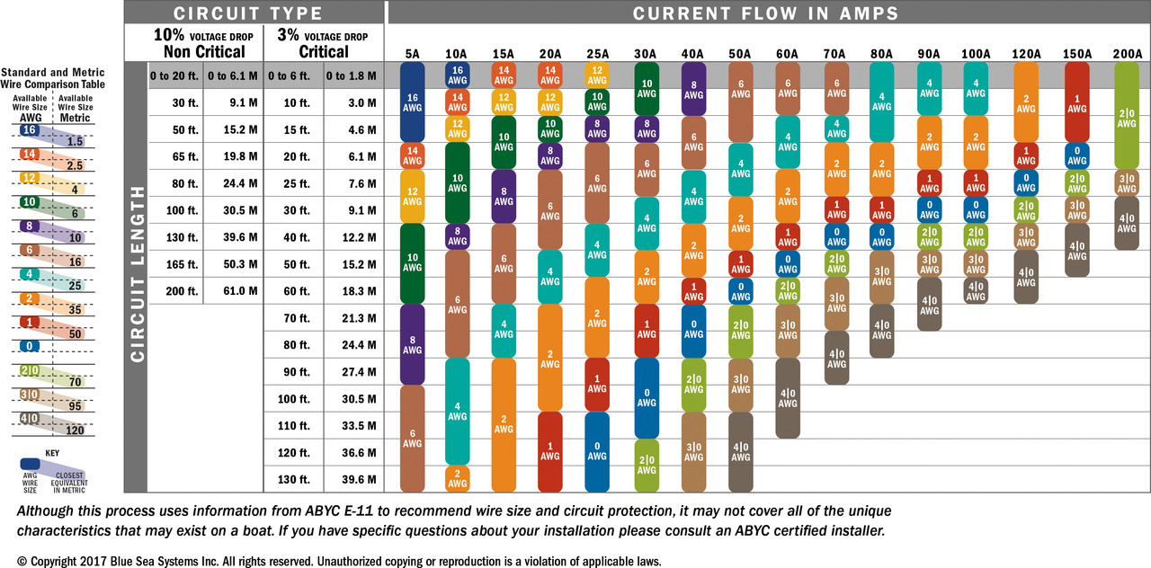
One thing to remember about wire gauge. The higher the number, the smaller the wire. 8 gauge is larger wire than 18 gauge.
Let's use a DC-DC charger for example.
I have a 20a DC-DC charger. This charger is fed directly from my battery. The charger will pull as much current as it can, up to 20A. Over a distance of 15ft, 12v circuits have a voltage drop. Based on the chart linked above, I would need to use a minimum gauge wire that is 12 gauge. Using 12 gauge wire though, there would be a 10% drop in amps available at the charger. Because of this, at the battery, the charger would pull 22A. 20A over a 15 foot run of wire would be a lot, so in that instance, it would be better to minimize both heat, and voltage drop by using 10gauge wire. This means that at the battery, the charger would only pull 20.6A instead of 22,and the wire would get as warm, minimizing fire risk.
Could you feed a 20A draw using 18 gauge wire? Sure, but that wire would get rather hot, melt the insulation, and likely start a fire. This is why wire gauge is important.
Fuses.
Fuses are critical for safe operation of 12v circuits. You always want to have a fuse that corresponds to the amperage draw of a given circuit, and place that fuse as close to the power source as possible.
Let's take our previous example using 18gauge wire.
If we placed a 20a fuse close to the battery, as the wire heated up, and the insulation melted, that wire would contact something metal, causing a short. A short would draw as much current as it can. In this case, let's say 60A. 60A would be more than our 20A fuse could handle, causing the fuse to pop. This would break the circuit, and cut the flow of current to the wire, preventing a fire.
Obviously, this is an extreme example, but it illustrates the importance of using fuses. By placing the fuse close to the battery though, the current draw would be considerably more than 20A at the battery. Because we put a 20A fuse there, that fuse would pop before the wire got hot, preventing the wire from getting hot, melting the insulation, and causing a short in the first place.
Relays and switches
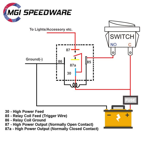
Relays are used to turn a high amperage circuit on and off using a low amperage circuit.
A common application to this is turning offroad lights on and off.
Your high amperage draw (lights) draw 20A. You can use a switch that draws 1a to turn the lights on and off. If you only have one light, this might be overkill, but switches have the ability to turn on multiple Relays with a single switch.
For example, I have multiple accessory ports at the back of my drawer system, as well as a voltage gauge. These ports run off two Relays, each powered by a 20A fuse. These are turned on by a single switch. This way, I'm able to run separate wires to each side, minimizing both heat, and voltage drop. A single wire would need both a 40A fuse, and need to be much larger to accommodate the heat generated by a 40A draw.
Most Relays are 5pin,and wired in this fashion (though you can also do switched ground using a relay, but that's a different and less common way of doing it).
Types of switches.
There are three main types of switches you'll find.
Small 3 pin switches like these:
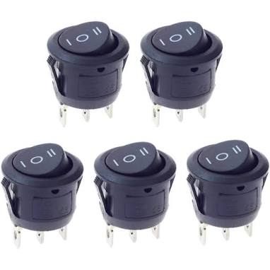
These switches have a positive, negative and accessory circuit, or are 3 position switches power in-acc1-acc2-ground)
The most common type of switch you'll see looks like this:
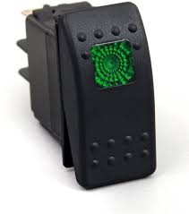
These switches are available in 3 pin, 5 pin and 7 pin.
3 pin switches are the same as the small 3 pin switches.
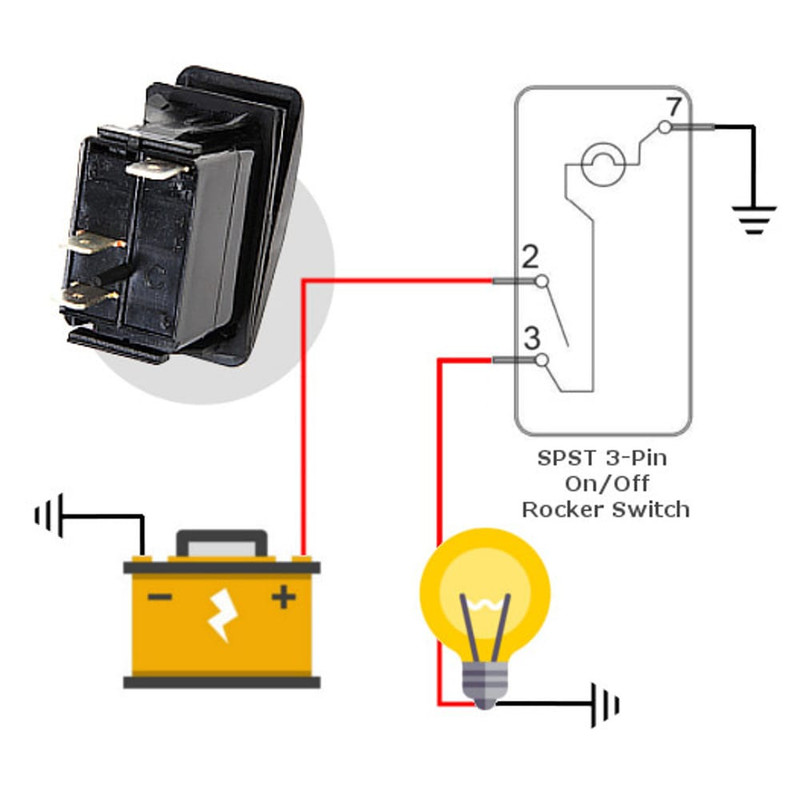
5 pin switches have an added illumination circuit with separate ground,
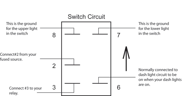
and 7 pin switches work like 3 position small switches, with an added illumination circuit.
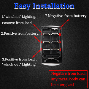
With all these switches, the positive out can run to the low voltage input of a relay to switch a higher amperage circuit.
Fuseblocks
Most auxiliary electrical systems use fuseblocks. This makes wiring things simpler, as you can run one large wire to s single location, and add circuits to the fuseblocks as needed.
To give you an example, once you grasp the basics of a 12v system, and how Relays, fuses, switches work, and how to size your wire based on the load you need to pull, it becomes easy to build a system that looks like this from the ground up.
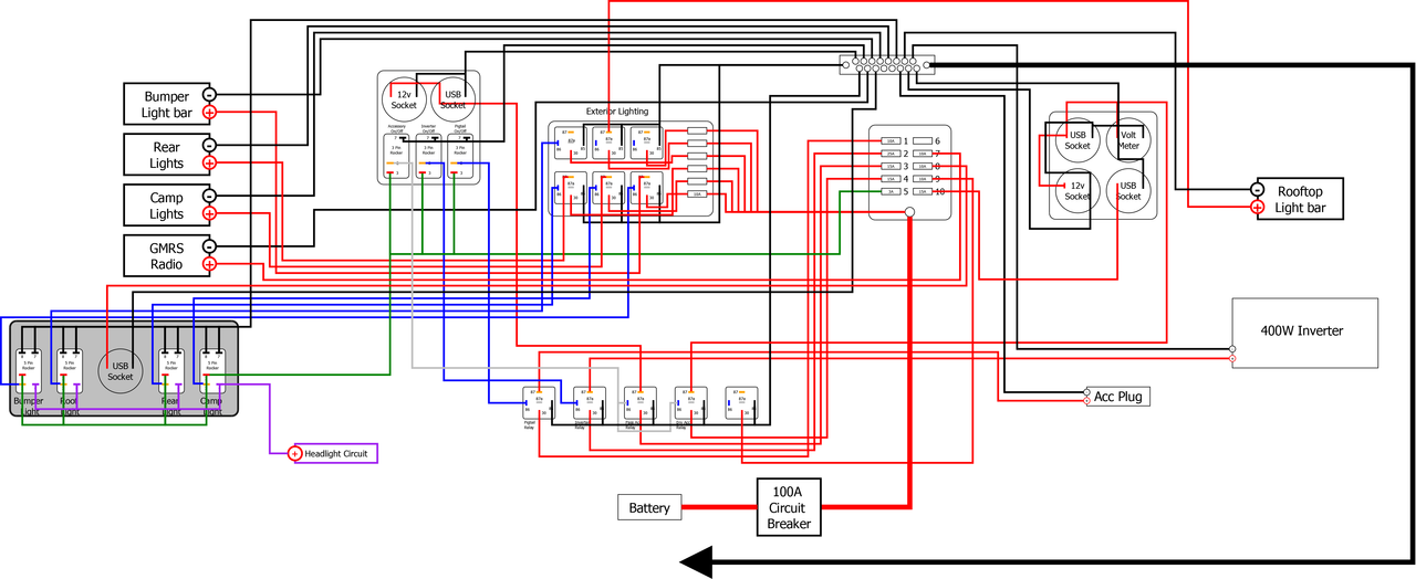
Hope that helps. Feel free to ask questions in this section of the forum, and we'll try and get them answered for you!
12v basics
Automotive electronics work on a 12 volt system. This is different than the 120v system in your house.
12v is what's referred to as DC, or direct current. Dc current is different than the 120v ac current coming into your home.
If you would like to understand the technical differences between 12v and 120v,id recommend the following article:
Electrical Voltage Explained - What Is It and How Does It Work ?
12v is generally simple to work with. Power comes in (positive or +) and goes out to ground (usually the battery negative or -) to complete a circuit.
That is a dc circuit in its simplest form.
There are lots of things to consider with dc circuits.
There are different gauges of wire that is capable of carrying different amounts of current different distances. This is because wires have resistance as the current passes through them. This resistance translates to heat. The wires need to be large enough to handle the heat generated by the resistance of the wire.
Basically remember this one simple rule.
Current (A) + Distance = gauge
The more current you need, and the farther it needs to go, the larger the wire needs to be.
The following chart shows what gauge of wire you need to use based on the amperage draw for a given circuit and how far it needs to run.

One thing to remember about wire gauge. The higher the number, the smaller the wire. 8 gauge is larger wire than 18 gauge.
Let's use a DC-DC charger for example.
I have a 20a DC-DC charger. This charger is fed directly from my battery. The charger will pull as much current as it can, up to 20A. Over a distance of 15ft, 12v circuits have a voltage drop. Based on the chart linked above, I would need to use a minimum gauge wire that is 12 gauge. Using 12 gauge wire though, there would be a 10% drop in amps available at the charger. Because of this, at the battery, the charger would pull 22A. 20A over a 15 foot run of wire would be a lot, so in that instance, it would be better to minimize both heat, and voltage drop by using 10gauge wire. This means that at the battery, the charger would only pull 20.6A instead of 22,and the wire would get as warm, minimizing fire risk.
Could you feed a 20A draw using 18 gauge wire? Sure, but that wire would get rather hot, melt the insulation, and likely start a fire. This is why wire gauge is important.
Fuses.
Fuses are critical for safe operation of 12v circuits. You always want to have a fuse that corresponds to the amperage draw of a given circuit, and place that fuse as close to the power source as possible.
Let's take our previous example using 18gauge wire.
If we placed a 20a fuse close to the battery, as the wire heated up, and the insulation melted, that wire would contact something metal, causing a short. A short would draw as much current as it can. In this case, let's say 60A. 60A would be more than our 20A fuse could handle, causing the fuse to pop. This would break the circuit, and cut the flow of current to the wire, preventing a fire.
Obviously, this is an extreme example, but it illustrates the importance of using fuses. By placing the fuse close to the battery though, the current draw would be considerably more than 20A at the battery. Because we put a 20A fuse there, that fuse would pop before the wire got hot, preventing the wire from getting hot, melting the insulation, and causing a short in the first place.
Relays and switches
Relays are used to turn a high amperage circuit on and off using a low amperage circuit.
A common application to this is turning offroad lights on and off.
Your high amperage draw (lights) draw 20A. You can use a switch that draws 1a to turn the lights on and off. If you only have one light, this might be overkill, but switches have the ability to turn on multiple Relays with a single switch.
For example, I have multiple accessory ports at the back of my drawer system, as well as a voltage gauge. These ports run off two Relays, each powered by a 20A fuse. These are turned on by a single switch. This way, I'm able to run separate wires to each side, minimizing both heat, and voltage drop. A single wire would need both a 40A fuse, and need to be much larger to accommodate the heat generated by a 40A draw.
Most Relays are 5pin,and wired in this fashion (though you can also do switched ground using a relay, but that's a different and less common way of doing it).

Types of switches.
There are three main types of switches you'll find.
Small 3 pin switches like these:
These switches have a positive, negative and accessory circuit, or are 3 position switches power in-acc1-acc2-ground)
The most common type of switch you'll see looks like this:
These switches are available in 3 pin, 5 pin and 7 pin.
3 pin switches are the same as the small 3 pin switches.

5 pin switches have an added illumination circuit with separate ground,

and 7 pin switches work like 3 position small switches, with an added illumination circuit.

With all these switches, the positive out can run to the low voltage input of a relay to switch a higher amperage circuit.
Fuseblocks
Most auxiliary electrical systems use fuseblocks. This makes wiring things simpler, as you can run one large wire to s single location, and add circuits to the fuseblocks as needed.
To give you an example, once you grasp the basics of a 12v system, and how Relays, fuses, switches work, and how to size your wire based on the load you need to pull, it becomes easy to build a system that looks like this from the ground up.

Hope that helps. Feel free to ask questions in this section of the forum, and we'll try and get them answered for you!


