
Good morning!
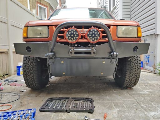
So, I have one of the Rough Country switch controllers, and although it's been in for a while (and gets power), only yesterday did I begin to hook it up. I attempted to wire two Nilight 51w floods to it.
The switch panel has a fuse and relay already as a part of the line, so I did not wire either of those into the two lights. However, wiring them in...must have been user operator error. No light. Not even a flicker to the lights.
I did hear clicking, so I am assuming that I blew the fuse. I will be taking it all apart to make sure that everything works before attempting again.
My question is: how to you wire the lights typically? I wired the two together with the negs all together, power all together, and to the panel. Is that the proper way to do it?