-
Guest, UPDATE We went through the site migration runbook and completed all steps. We will need to complete the migration next week, but will leave the forums up for the weekend. A few days after maintenance, a major upgrade revision to the forum site will occur.


Off-Road Ranger I
Thanks! It's been a dream project for sure :)Great build!
Got a late start out at the shop tonight but I did get the inner tubes cut/bent/fishmouthed/tacked in:
(8/13/18 edit: linked incorrect photo)
Last edited:

Influencer I
Off-Road Ranger I
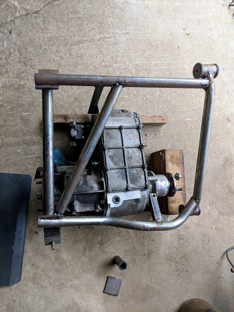
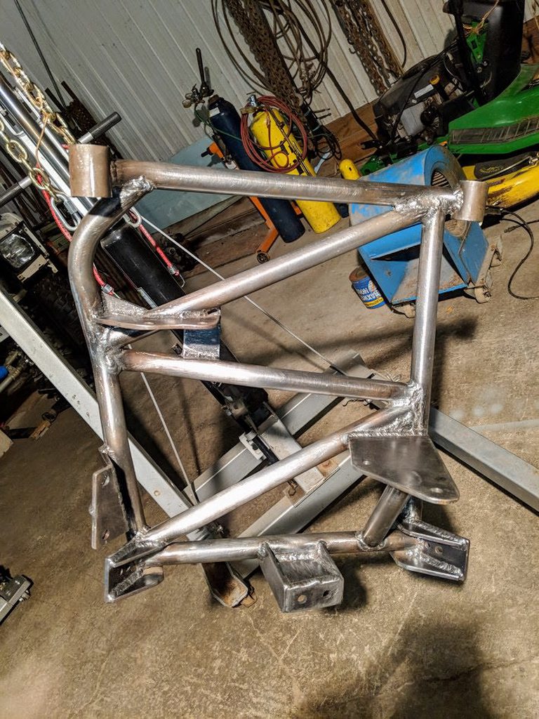
Now that I've dragged it out from underneath I can go to work on the tubes 'n tabs for affixing the transfer box to the uh... assembly/cradle/cross-member/thingy? Here with the 3 tubes triangulating the outer "box" of initial tubes:
One of which needed a little bit of creative bending to clear the housing's oil pan, & ought to be just a touch above the frame cross-member's lowest point. It shouldn't compromise the stiffness of the assembly much & if anything all this tubing will make for some legit transfer-case armor:
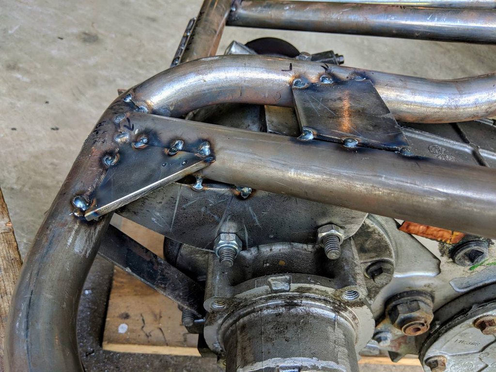
The first mounting bracket, along the passenger side near the front driveshaft output, was a cinch. Simple pair of plates at mirrored angles:

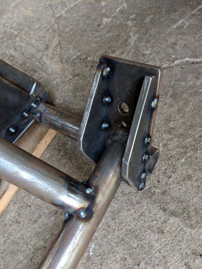
The next bracket, also on the passenger side, at the rear driveshaft output was a handful. Had to snake it around 3 tubes, with a pair of gussets across the ends for good measure:
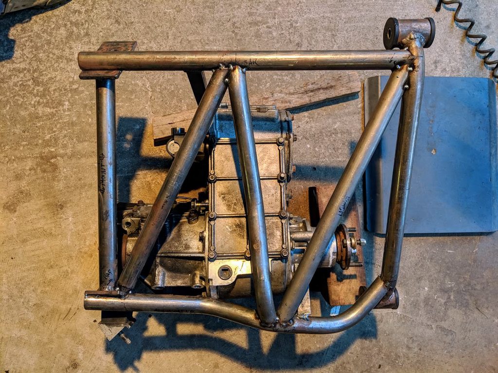
The final bracket was the most critical, seeing as it bolts up right under the input & will be responsible for keeping the pair of yokes aligned under load. I want this side to move as little as I can manage so I tossed in a kicker tube (triangles are strong!) running from the front lateral to right between the pair of bolts:

I might slot a few holes in the new brackets too, guess it really depends on how well my temporary legs did at keeping everything in place while I was under there before. Now I just need to test fit it one last time, tack in the rear transmission mount bracket (will go straight up from the tube between the 2 front plate brackets), & burn it all in!
One of which needed a little bit of creative bending to clear the housing's oil pan, & ought to be just a touch above the frame cross-member's lowest point. It shouldn't compromise the stiffness of the assembly much & if anything all this tubing will make for some legit transfer-case armor:
The first mounting bracket, along the passenger side near the front driveshaft output, was a cinch. Simple pair of plates at mirrored angles:
The next bracket, also on the passenger side, at the rear driveshaft output was a handful. Had to snake it around 3 tubes, with a pair of gussets across the ends for good measure:
The final bracket was the most critical, seeing as it bolts up right under the input & will be responsible for keeping the pair of yokes aligned under load. I want this side to move as little as I can manage so I tossed in a kicker tube (triangles are strong!) running from the front lateral to right between the pair of bolts:
I might slot a few holes in the new brackets too, guess it really depends on how well my temporary legs did at keeping everything in place while I was under there before. Now I just need to test fit it one last time, tack in the rear transmission mount bracket (will go straight up from the tube between the 2 front plate brackets), & burn it all in!

Good job!Now that I've dragged it out from underneath I can go to work on the tubes 'n tabs for affixing the transfer box to the uh... assembly/cradle/cross-member/thingy? Here with the 3 tubes triangulating the outer "box" of initial tubes:
One of which needed a little bit of creative bending to clear the housing's oil pan, & ought to be just a touch above the frame cross-member's lowest point. It shouldn't compromise the stiffness of the assembly much & if anything all this tubing will make for some legit transfer-case armor:
The first mounting bracket, along the passenger side near the front driveshaft output, was a cinch. Simple pair of plates at mirrored angles:
The next bracket, also on the passenger side, at the rear driveshaft output was a handful. Had to snake it around 3 tubes, with a pair of gussets across the ends for good measure:
The final bracket was the most critical, seeing as it bolts up right under the input & will be responsible for keeping the pair of yokes aligned under load. I want this side to move as little as I can manage so I tossed in a kicker tube (triangles are strong!) running from the front lateral to right between the pair of bolts:
I might slot a few holes in the new brackets too, guess it really depends on how well my temporary legs did at keeping everything in place while I was under there before. Now I just need to test fit it one last time, tack in the rear transmission mount bracket (will go straight up from the tube between the 2 front plate brackets), & burn it all in!
You have to put this thing on the scales when done! I am curious as to how much this thing weighs.
Off-Road Ranger I
It's no lightweight, that's for sure! And it's hardly done either, still going to build: Rock sliders, Bumper (rear w/swingout), Roll Cage (6-8 point), 3-link Front & 4-link Rear Suspension (dom tube, heims), taller tires (37"), & much bigger axles (lockers, full float, lockouts, etc).
BUT GVWR? If my estimates pan out then I'll be approaching the limit just before I'm ready to build the custom suspension & axles that'll throw that limit right out the window.
BUT GVWR? If my estimates pan out then I'll be approaching the limit just before I'm ready to build the custom suspension & axles that'll throw that limit right out the window.
Off-Road Ranger I
Same here! Going to do it ASAP once it's on the road so I can toss my current coil springs for a properly weight-rated set.Good job!
You have to put this thing on the scales when done! I am curious as to how much this thing weighs.
Off-Road Ranger I
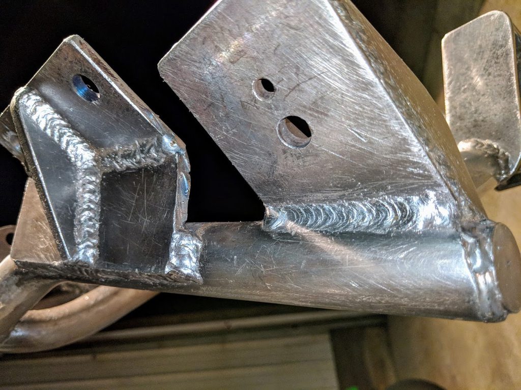
Added a little bit more bracing to the forward mount plates at the recommendation of a friend:
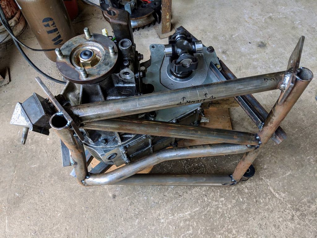
And while it's out on the ground I removed my transfer-case's large front driveshaft flange for a smaller rear flange. So now they both match front to back, which is what will allow me to run identical driveshafts:

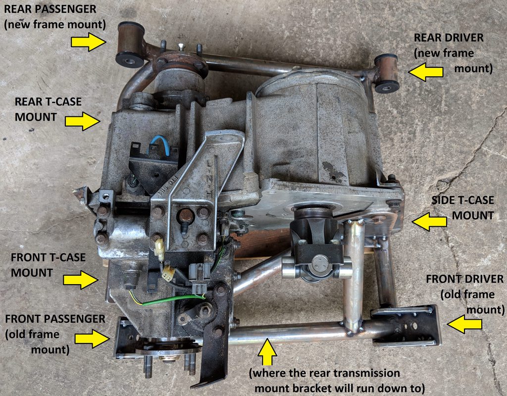
Since this "divorced" method of mounting a transfer-case is rare, especially with a subframe like this, here's a visual break down of the key points:
And while it's out on the ground I removed my transfer-case's large front driveshaft flange for a smaller rear flange. So now they both match front to back, which is what will allow me to run identical driveshafts:
Since this "divorced" method of mounting a transfer-case is rare, especially with a subframe like this, here's a visual break down of the key points:
Looks like a substantial transfer case mount.
Curious to hear what the completed vehicle ends up weighing.
Curious to hear what the completed vehicle ends up weighing.
Off-Road Ranger I
Got everything burned in tonight & the subframe is officially complete!
Test fitting showed that everything lined up straight with good clearances & leaves it tucked up nicely once the frame crossmember goes back in. More practice with the MIG is slowly improving my welds, just have to keep up with it to keep the skills honed:
Several hours of welding, wire wheeling, & filing smooth resulted in a fine looking bit of kit:
Etch primer base coat goes on first, nasty but the the good stuff tends to be:
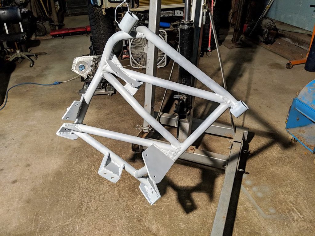
And the final base coat..... job done! Time to get the thing in there & move on to work that'll have it making some smoke!

Test fitting showed that everything lined up straight with good clearances & leaves it tucked up nicely once the frame crossmember goes back in. More practice with the MIG is slowly improving my welds, just have to keep up with it to keep the skills honed:
Several hours of welding, wire wheeling, & filing smooth resulted in a fine looking bit of kit:
Etch primer base coat goes on first, nasty but the the good stuff tends to be:
And the final base coat..... job done! Time to get the thing in there & move on to work that'll have it making some smoke!
Off-Road Ranger I
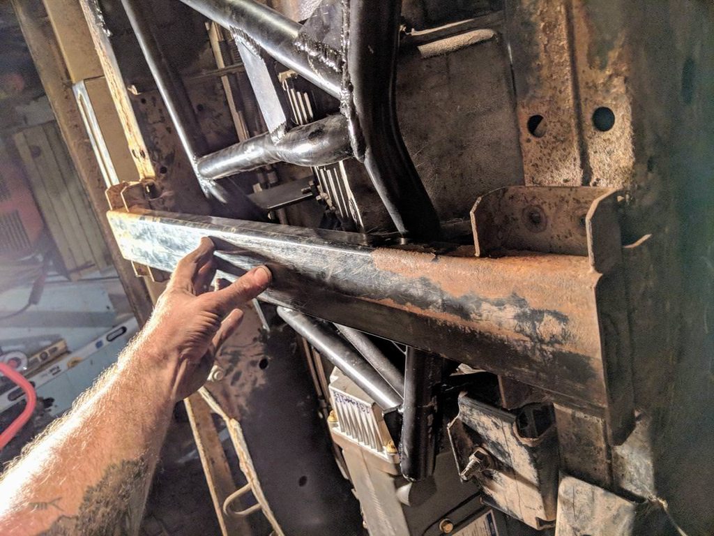
It's officially up in there & all the weight is on the chassis... the truck's finally able to roll again! 
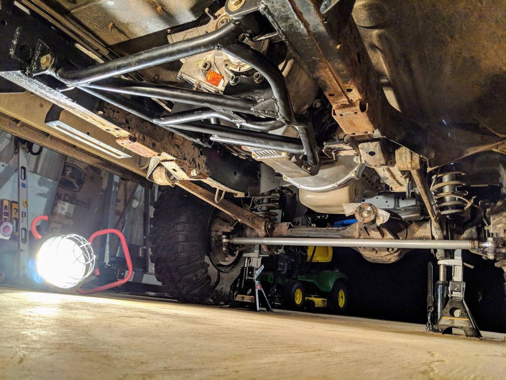
The old frame-rail crossmember fits perfect under the tubing of the new subframe, which worked out as planned, keeping the new subframe just a tick above it & safe from getting hung up. All the tube bending work to wrap around it all paid off:
Wicked straight in there! Angles are all on point now that it's completely hanging under it's own weight: Yaw @ zero°, Roll @ zero°, Pitch @ the Cummins prescribed 3° with front end higher:
Off-Road Ranger I
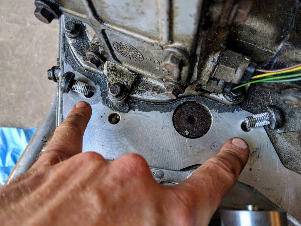
I skipped a few details earlier that could be helpful... if you were nutty enough to go down this road yourself. The subframe is still up in there, just didn't want to forget to mention these things: First off I kept getting a random seep of gear oil that was fooling me into thinking the input seal failed. As it turns out these 2 bolt holes are through the case & into the oil galleries, so don't forget to plug 'em!
Also now I have TWO transfer-case cables! :D This generation of Discovery 2's (2001.5~2003) are lacking the CDL & so are technically AWD & not capable of "full-time" 4-wheel-drive like most other Rovers & Land Cruisers. For some bizarre reason the Rover engineers decided to try & save a few pounds by making a change to the transfer-case internals for a brief bit of it's production. The additional component that separates these trucks from most 4x4's is the third differential in the transfer-case, aka the center differential. Which I can now lock solid into "full-time" via the additional cable with this version of the LT230, extracted from a year later Discovery 2 that was reintroduced once the engineers realized their blunder. It's a huge capability upgrade, in addition to an upgrade in durability (non-locking Disco's can easily overheat their open center-diffs in extended low traction situations).
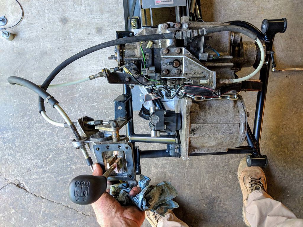
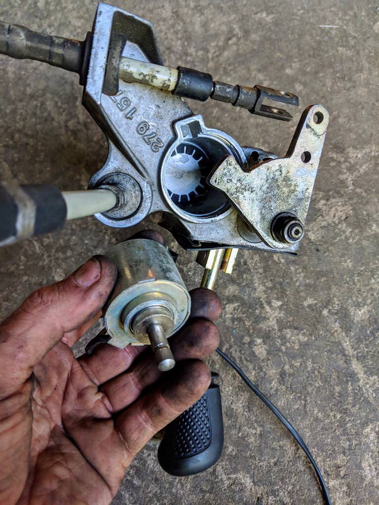
While I was in there I yanked & chucked the lock-out solenoid that's buried in the shifter assembly's base. Saves me a load of unneeded wiring, switches, & relays. Between the lever assembly & cables & shift forks there's enough resistance to not worry about engaging unexpectedly:
Also now I have TWO transfer-case cables! :D This generation of Discovery 2's (2001.5~2003) are lacking the CDL & so are technically AWD & not capable of "full-time" 4-wheel-drive like most other Rovers & Land Cruisers. For some bizarre reason the Rover engineers decided to try & save a few pounds by making a change to the transfer-case internals for a brief bit of it's production. The additional component that separates these trucks from most 4x4's is the third differential in the transfer-case, aka the center differential. Which I can now lock solid into "full-time" via the additional cable with this version of the LT230, extracted from a year later Discovery 2 that was reintroduced once the engineers realized their blunder. It's a huge capability upgrade, in addition to an upgrade in durability (non-locking Disco's can easily overheat their open center-diffs in extended low traction situations).
While I was in there I yanked & chucked the lock-out solenoid that's buried in the shifter assembly's base. Saves me a load of unneeded wiring, switches, & relays. Between the lever assembly & cables & shift forks there's enough resistance to not worry about engaging unexpectedly:
Off-Road Ranger I
It's fairly long at 17 minutes, but then I guess that many hours building the subframe packed into 1 video would be haha!
Off-Road Ranger I
Time for exhaust manifold mods!
The victim is a used 6BT manifold (the 6-cylinder version of my 4-cylinder powerplant, found mostly in Dodge trucks). Plan is to use this to move my turbo away from the engine & down as well by using big brother's manifold:
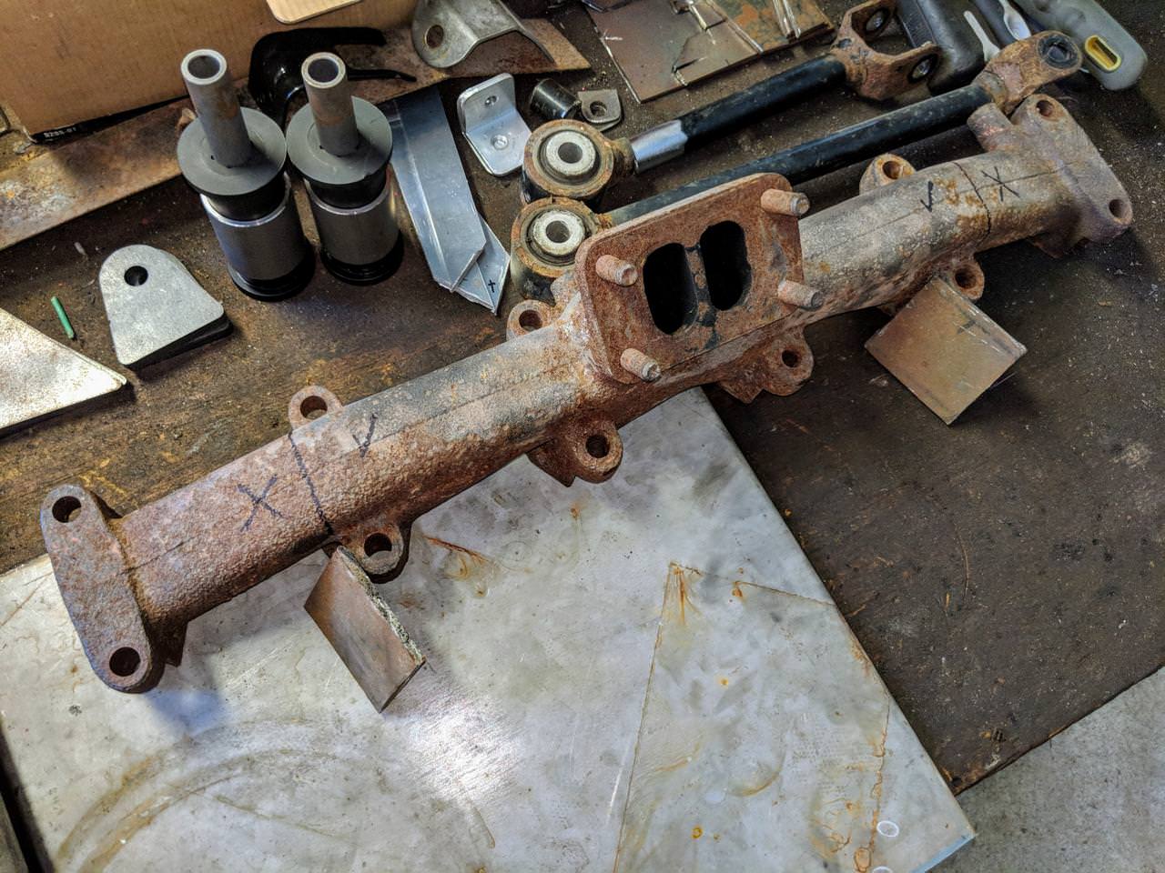
I started by chopping off the pair of extra ports from either end, leaving the original flange right in the center of the remaining 4:
After a good working over with a wire brush I fired up the heat wrench & got it prepped for welding with an even preheat:
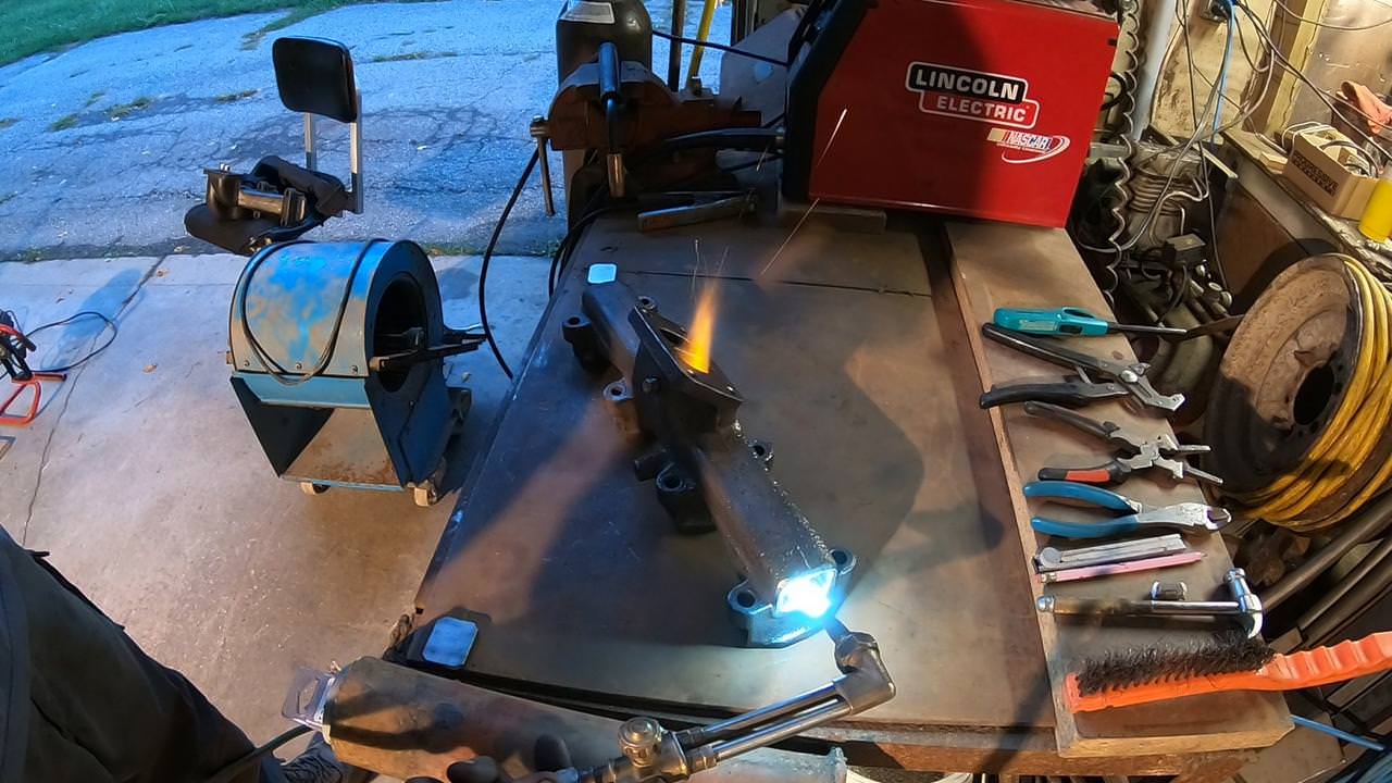
I cut up 1/4" plate for end caps, cranked the welder up to full power amperage, & sunk a run of .035" wire into it:
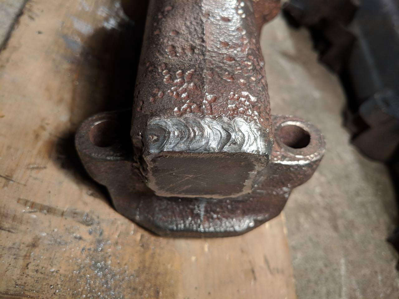
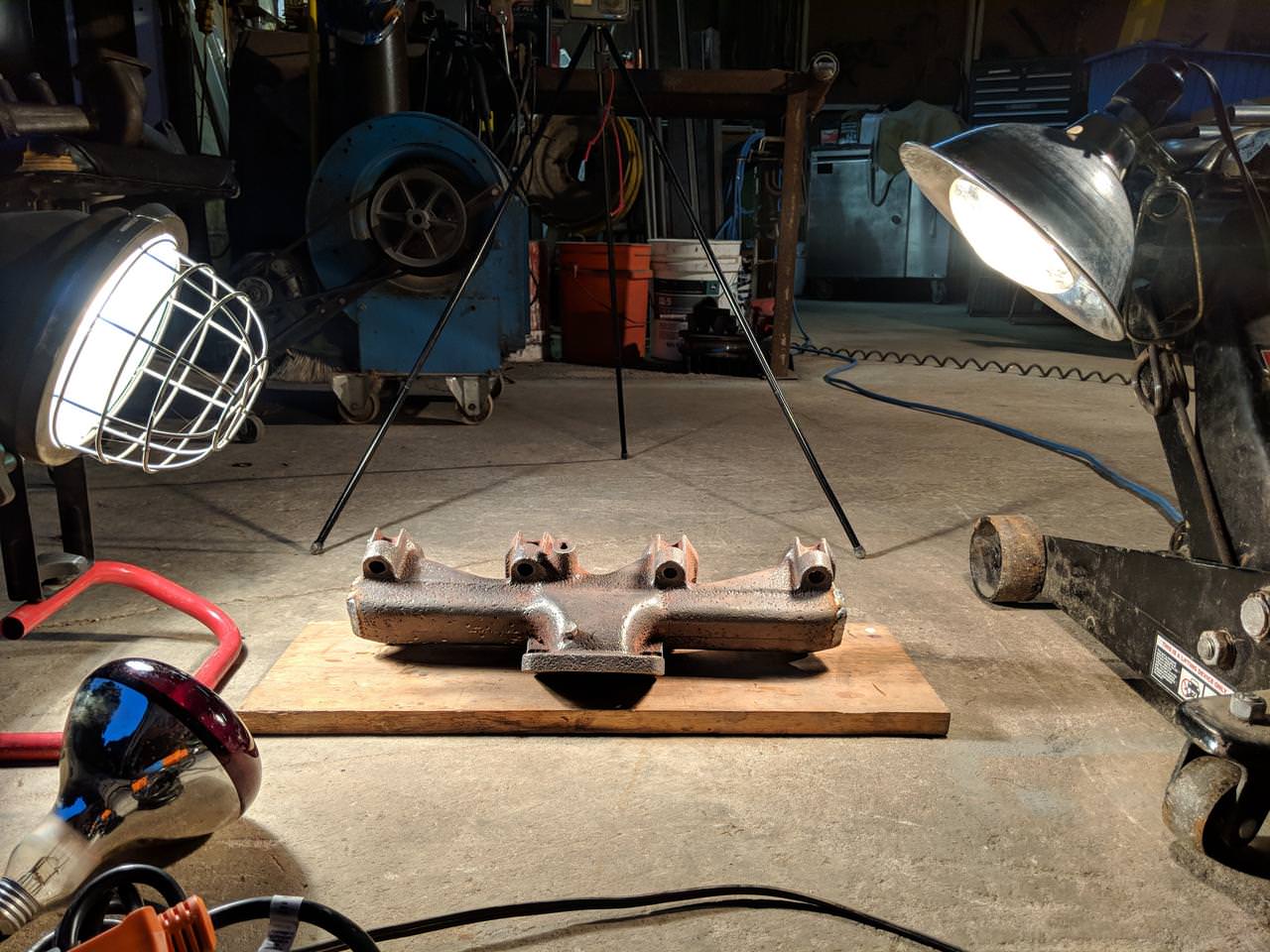
I wanted to pay extra special attention to avoiding cracks, so I forced it to cool down as slowly as I could, aided by lamps:
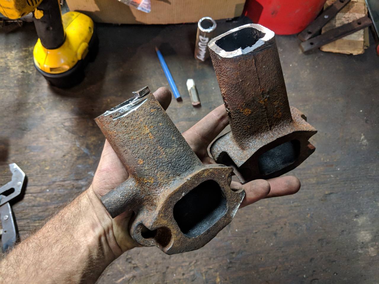
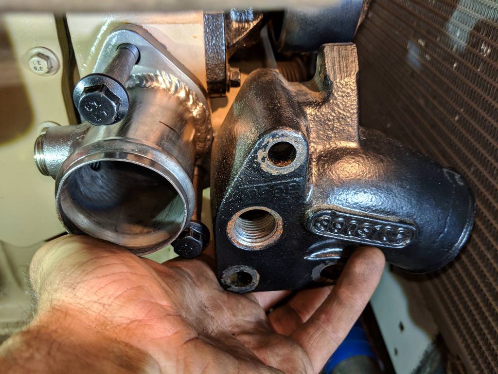
Equal-length top-mount on left, original low-end-mount in center, & my new cut 6BT manifold on the right to compare:
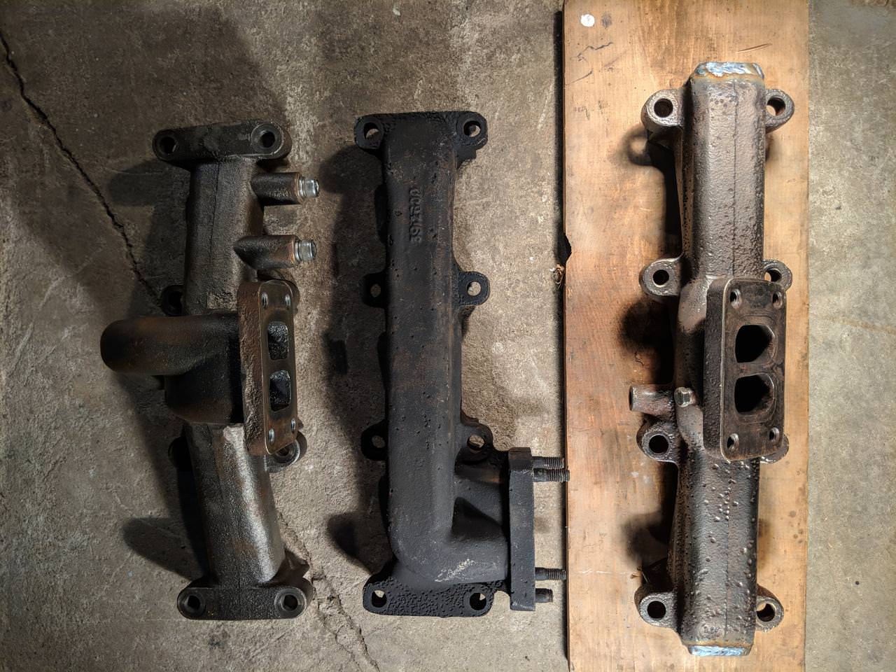
Much better! Lower down from the hood line, farther away from the injector lines, & provides me even better routing for intake + charge piping than the equal-length top-mount manifold could:

Now to wrap up some power steering pump mods so I can plumb air & water... closer every day to firing it up again!
The victim is a used 6BT manifold (the 6-cylinder version of my 4-cylinder powerplant, found mostly in Dodge trucks). Plan is to use this to move my turbo away from the engine & down as well by using big brother's manifold:
I started by chopping off the pair of extra ports from either end, leaving the original flange right in the center of the remaining 4:
After a good working over with a wire brush I fired up the heat wrench & got it prepped for welding with an even preheat:
I cut up 1/4" plate for end caps, cranked the welder up to full power amperage, & sunk a run of .035" wire into it:
I wanted to pay extra special attention to avoiding cracks, so I forced it to cool down as slowly as I could, aided by lamps:
Equal-length top-mount on left, original low-end-mount in center, & my new cut 6BT manifold on the right to compare:
Much better! Lower down from the hood line, farther away from the injector lines, & provides me even better routing for intake + charge piping than the equal-length top-mount manifold could:
Now to wrap up some power steering pump mods so I can plumb air & water... closer every day to firing it up again!
Off-Road Ranger I
Off-Road Ranger I
The list of things in the way of firing this engine up again (after nearly 9 months now) is getting pretty short! All I have between me & making some smoke is plumbing & a starter cable. Next thing on that list is wrapping up my steering system mods & getting them sealed from end to end.
First step is getting a power-steering-pump support bracket made up. It's a tight area, but with the help of some CAD templates (cardboard aided drafting) I was able to buzz together a few strips of 1" flat-stock to keep the vacuum-pump/steering-pump combo's weight from leaning too hard off the timing cover & cracking it:
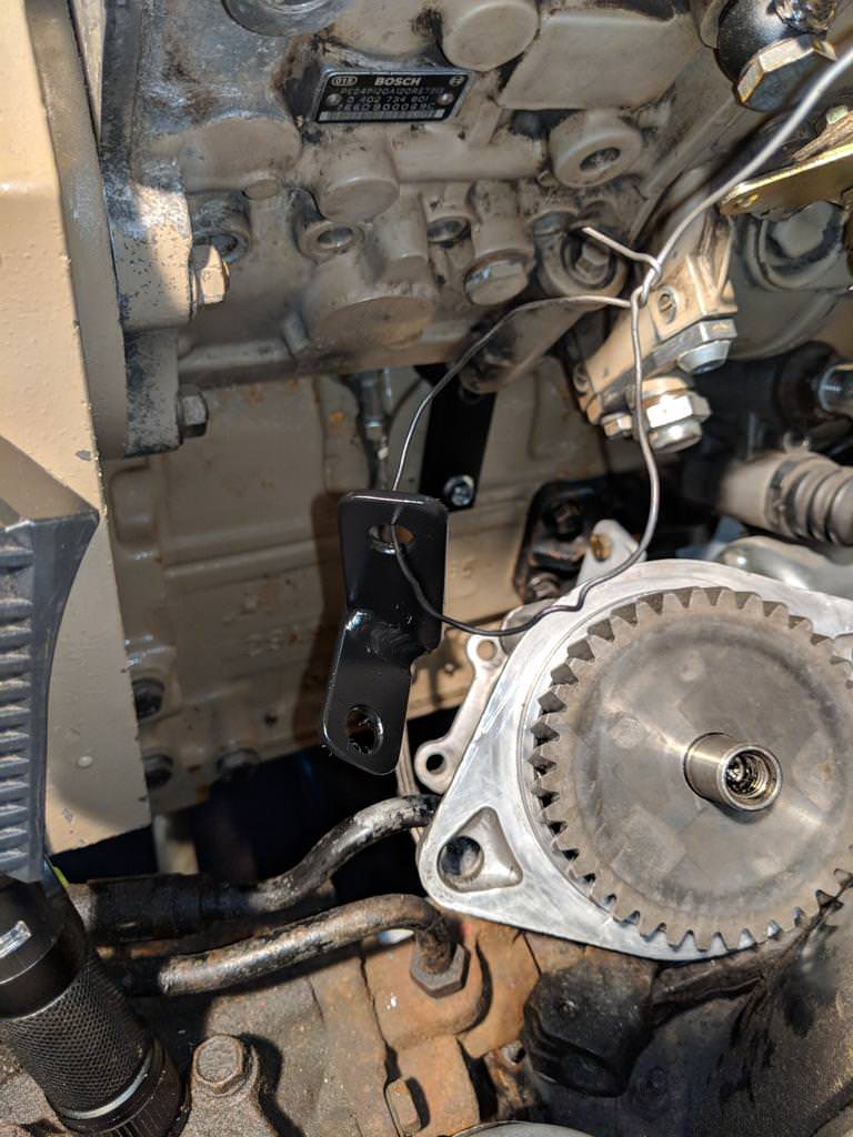
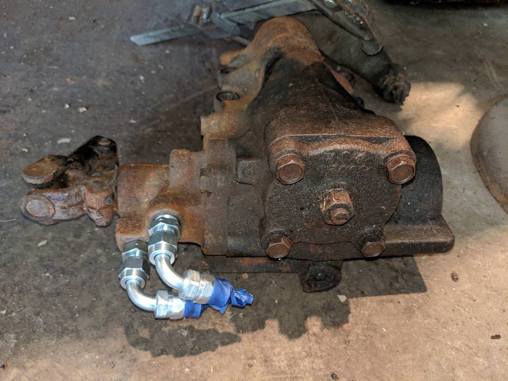
I'm adding a fluid-cooler in the system & I'm really liking the way all the AN lines/fittings have been going together on multiple projects so far, figure the best way to plumb everything is continue with it for the steering. The new Land Cruiser steering-gear needs a couple of of oddball fittings (M17x1.5 & M16x1.5 inverted flare) before I can run the new -6AN teflon stainless lines:
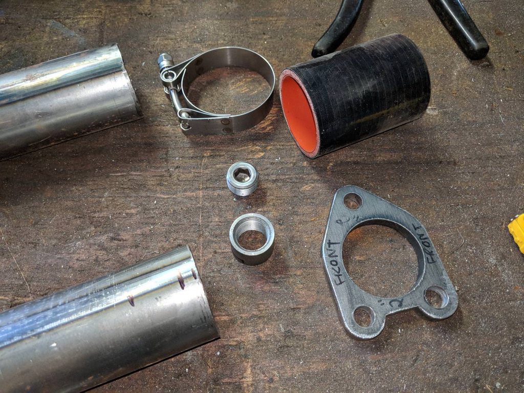
Other then the lines, last thing that needs sealing up is the steering-pump reservoir. I tried to braze over my MIG welds for the modified fill neck to seal it up tight... but that was a bit of a disaster, so I'm going to wait to get help from a friend to TIG weld it like I should have in the first place. Until then I'm going to move on to the new lower coolant inlet tube I need to build. The original one is too big & at a funny angle that doesn't aim anywhere near towards the lower radiator's tube. Here are the parts (2" tube, 3-bolt flange, npt bung, etc) I'm starting with:
I'm genuinely shocked how fantastic this "Jobber Do" bead forming tool works! I wasn't about to drop a minimum of $500 on a bead-roller, so when I found this $60 tool made by a vintage race car builder/driver I was all about it:

Here's the finished custom lower coolant pipe beside the original:
First step is getting a power-steering-pump support bracket made up. It's a tight area, but with the help of some CAD templates (cardboard aided drafting) I was able to buzz together a few strips of 1" flat-stock to keep the vacuum-pump/steering-pump combo's weight from leaning too hard off the timing cover & cracking it:
I'm adding a fluid-cooler in the system & I'm really liking the way all the AN lines/fittings have been going together on multiple projects so far, figure the best way to plumb everything is continue with it for the steering. The new Land Cruiser steering-gear needs a couple of of oddball fittings (M17x1.5 & M16x1.5 inverted flare) before I can run the new -6AN teflon stainless lines:
Other then the lines, last thing that needs sealing up is the steering-pump reservoir. I tried to braze over my MIG welds for the modified fill neck to seal it up tight... but that was a bit of a disaster, so I'm going to wait to get help from a friend to TIG weld it like I should have in the first place. Until then I'm going to move on to the new lower coolant inlet tube I need to build. The original one is too big & at a funny angle that doesn't aim anywhere near towards the lower radiator's tube. Here are the parts (2" tube, 3-bolt flange, npt bung, etc) I'm starting with:
I'm genuinely shocked how fantastic this "Jobber Do" bead forming tool works! I wasn't about to drop a minimum of $500 on a bead-roller, so when I found this $60 tool made by a vintage race car builder/driver I was all about it:
Here's the finished custom lower coolant pipe beside the original:
Off-Road Ranger I
Almost forgot that I had to modify a pulley to fit the alternator from my old engine to the new Cummins. The Bosch unit from my Rover has a 7-groove pulley versus the 4BT engine's pulleys that are 8 groove. Why the old alternator? Partly because it pumps out a generous 130 amps, but also because it has the wiring inside to easily hack into for my tachometer signal!
Took me a fair bit of digging around to find a pulley that could work for my odd combination, & even the one I did find was going to need some minor modifications. Here it is getting the mounting boss trimmed down flush with the back face of the outer diameter:
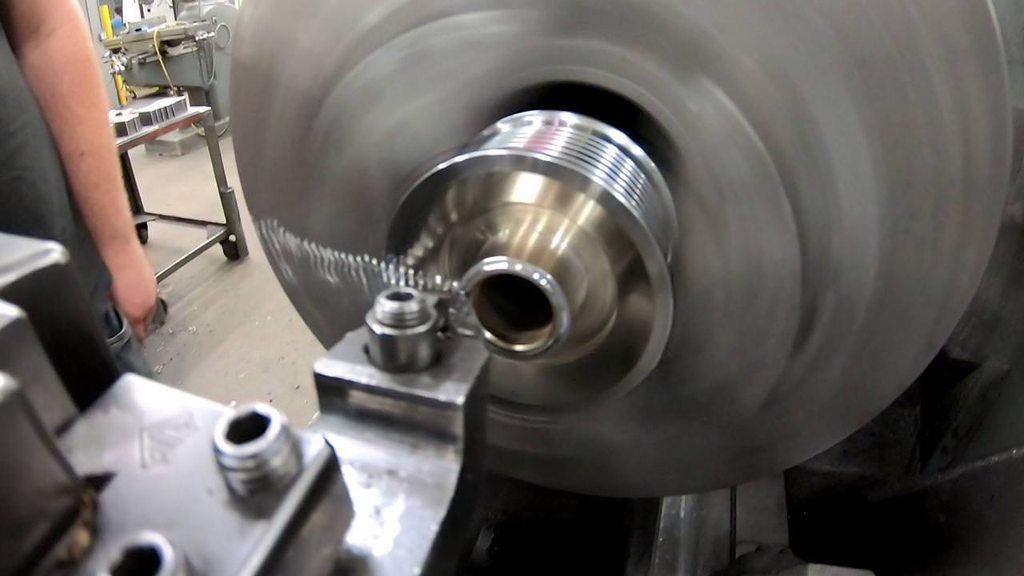
Sadly I can't use the pulley off the old Cummins alternator. Mainly because it has a much longer shaft, so I don't have any threads to grab hold of when it's placed on the Rover alternator, & also since it has a much higher offset from it's base. Now that this aftermarket pulley's trimmed down it fits great & lines right up with the old belt's witness marks:

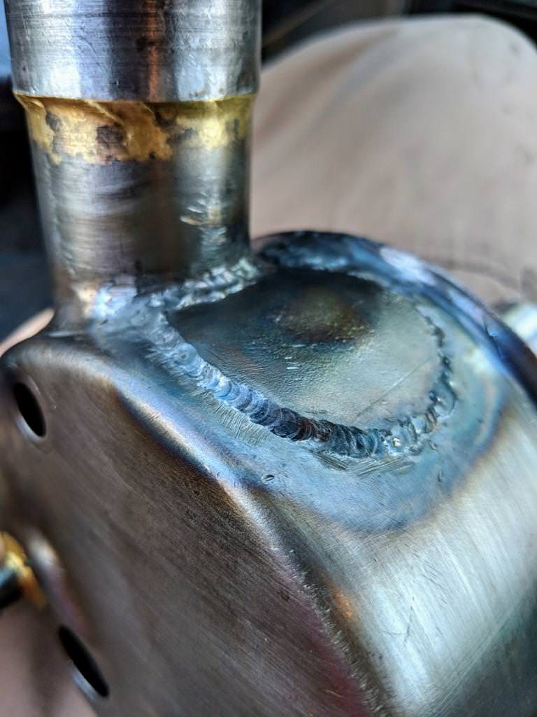
While I was there getting help from my friend (& learning anything I could while I was there) we also had a crack at TIG welding the plug over the hole where the old power-steering pump's reservoir fill-neck used to reside. I'd already MIG welded the fill-neck in it's new location BUT... then I tried my first attempt at brazing & things went all wrong when I got a little too aggressive with the heat. He did a bang-up job patching my mistake! Hopefully one of these days I can get a chance to sit down & try to learn 1/1000th what he knows using TIG:

I'm going to put a bead of seam sealer over all the welds as well... yeah it may be overkill. Looks like it's all welded up tight, but I think it's worth a fraction of a $ in proper sealer to be double sure before I paint it:
Took me a fair bit of digging around to find a pulley that could work for my odd combination, & even the one I did find was going to need some minor modifications. Here it is getting the mounting boss trimmed down flush with the back face of the outer diameter:
Sadly I can't use the pulley off the old Cummins alternator. Mainly because it has a much longer shaft, so I don't have any threads to grab hold of when it's placed on the Rover alternator, & also since it has a much higher offset from it's base. Now that this aftermarket pulley's trimmed down it fits great & lines right up with the old belt's witness marks:
While I was there getting help from my friend (& learning anything I could while I was there) we also had a crack at TIG welding the plug over the hole where the old power-steering pump's reservoir fill-neck used to reside. I'd already MIG welded the fill-neck in it's new location BUT... then I tried my first attempt at brazing & things went all wrong when I got a little too aggressive with the heat. He did a bang-up job patching my mistake! Hopefully one of these days I can get a chance to sit down & try to learn 1/1000th what he knows using TIG:
I'm going to put a bead of seam sealer over all the welds as well... yeah it may be overkill. Looks like it's all welded up tight, but I think it's worth a fraction of a $ in proper sealer to be double sure before I paint it:
Off-Road Ranger I
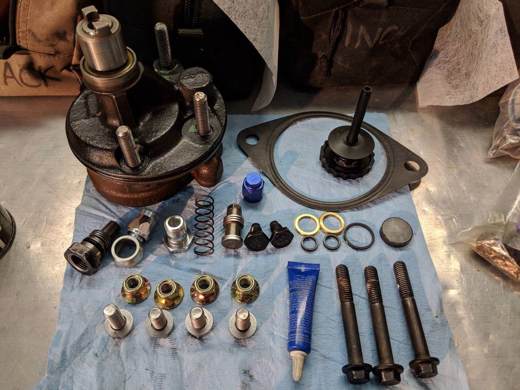
Sealed up tight & wearing a fresh coat:
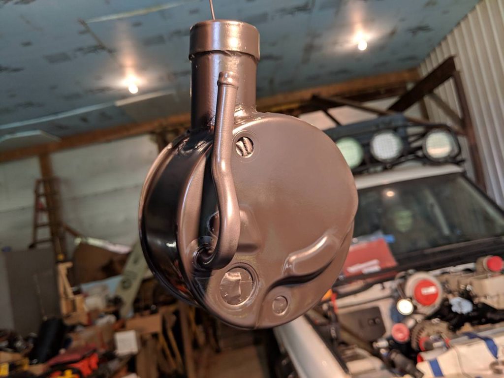
Ready to go back together with new hardware & the AN "banjo" fitting that clears the engine mount:
Reassembled & back in there! Fits great, well supported, but not so packed in that it's a nightmare to service:
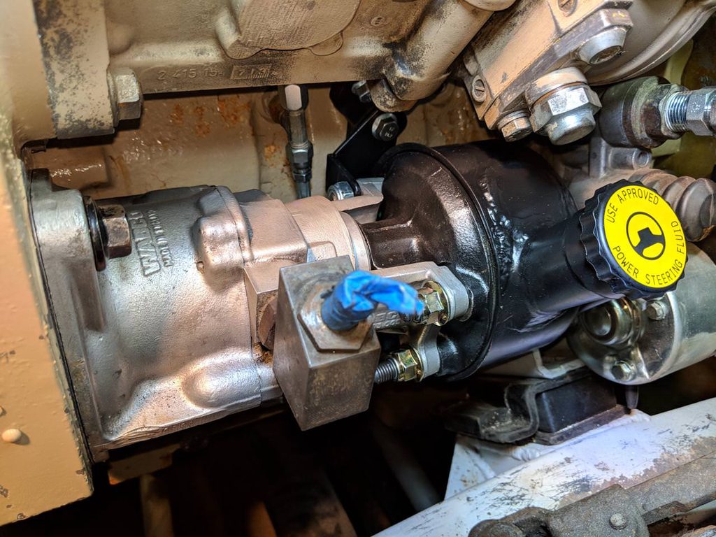
Now to get the stainless AN lines run & cooler mounted so I can get my radiator & charge cooler mounted too!
Ready to go back together with new hardware & the AN "banjo" fitting that clears the engine mount:
Reassembled & back in there! Fits great, well supported, but not so packed in that it's a nightmare to service:
Now to get the stainless AN lines run & cooler mounted so I can get my radiator & charge cooler mounted too!