My Ham Shack- Yaesu FT-2900- Icom IC-7100, and a leap into the digital world of radio

  • HTML tutorial

J.W.

Rank VI
Launch Member

Member III

3,432
Cincinnati
First Name
J
Last Name
W
Member #

17839

Mike,
Did you already get your antenna set up? What did you go with?
 

M Rose

Local Expert
Mod Team
Member

Advocate III

5,584
Northeast Oregon, United States
First Name
Michael
Last Name
Rose
Member #

20990

Ham/GMRS Callsign
W7FSB
Service Branch
US ARMY Retired
Mike,
Did you already get your antenna set up? What did you go with?
Antenna is up... I built my own design J-Pole... I used about 4 different write-ups to come up with my own solution. Sorry I didn’t take any pictures during the build... I have one thing left to do tomorrow and will take pictures of it... but until then I will describe what I did.

Materials:

3/4” copper pipe 10’ long
3/4” Copper T Connectors 2 each
3/4” copper pipe caps 4 each
#10 4” brass screw 1 each
#10 brass nut 2 each
SO 239 coax connector 1 each
RG58 Coax 50’
crimp on Coax Cable ends. 2 each
insulated solid 12 ga wire 2’
3/4“ hose clamp. 1 each
1 1/2” U-Bolt. 3 each

Tools:
Tubing cutter (hack saw)
tape measure
pen
soldering Iron
soldering torch
silver solder
3/16” drill bit
1/2” drill bit
electric drill

Procedure:
1. Cut The 3/4” copper pipe into 3 pieces... First 63” long, and second at 19” long.
2. Lay the 63” piece of pipe flat on the ground, place a T fitting at the bottom (cut end) face the second T fitting butted up against the first one and put the 19” piece of pipe facing parallel to the 63” pipe. This should form a weird “H” shape.
3. Using the torch heat both the 63” piece of pipe and the T fitting until the solder melts into the joint. Being careful not to knock the fitting off of square, set pipe and fitting to the side to cool.
4. Again Using the torch heat the second T fitting and the 19” piece of copper tubing and melt the solder into the joint. Set aside to cool, again being careful not to bump the fitting off of square from the pipe.
5. Drill a 1/2” hole into one Of the pipe caps. Set to the side. (we will call this cap B)
6. Drill a 3/16” hole into the center of another pipe cap.
7. thread one nut onto the 4” brass screw almost to the head of the screw.
8. Place screw through the of the copper plumbing cap with the 3/16” hole you drilled in step 6 With the head facing out. (This will be tuner A.)
9. Thread the second nut onto the brass screw until about 1/4” of threads are showing; sandwiching the cap between the two brass nuts. Run the external nut down tight onto the copper cap. The screw shouldn’t turn freely.
10. Flip the cap upside down and heat the cap until the solder flows. Solder the brass nut solid to the inside of the cap, but allow the external nut to still turn freely when done.
11. with The remaining unmeasured copper tubing cut off a piece that will fit inside cap B and mate it to the 19” pipe and T fitting, so that the cap fit flush with the base of the T.
12. solder the stub to both the T fitting and Cap B.
13. solder tuning Cap A onto the top of the 19” copper pipe.
14. Still working on the 1/4 wave stubby antenna (19” copper tube with T fitting, Tuning cap, and bottom cap) measure up 3“ from the top of the unused T fitting connector.
15. Drill a 3/16” hole in the 19” stubby antenna so that the bit leans towards the top of the antenna and is in line with the T stub.
16. Strip 1/4” of insulation from the 12 gauge wire.
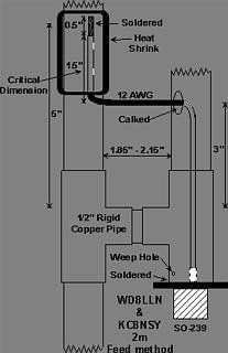
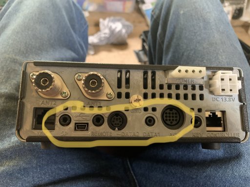
17. Solder the wire to the center of the SO-239 connector so that it is perfectly strait with the solder point. (See picture below)
18. Run the wire through the 1/2” hole in the bottom cap of the 1/4 wave antenna, and have the wire exit through the 3/16” hole in the side of the tubing.
19. Solder the PL 0259 connector to the base of the 19” antenna. Be careful not to melt the center of the connector (I found it best to use my soldering iron for this task). This finishes the 1/4 wave antenna.
20. Solder a cap onto the square end of the 63” piece of tubing. This finishes the 1/2 wave antenna.
21. Set both the 1/4 wave and 1/2 wave antennas so they are parellel to each other at 3 1/2” apart.
22. take the unused scrap tubing and cut a piece that will fill the gap between the 2 antennas.
23. Solder the stub just cut into the T’s of both antennas forming the “H”.
24. Cut the last piece of tubing to 26-27” and solder to the end of the long antenna.
25. Cap the reaming end and solder in place. (This makes the mount leg of the antenna)
26. On the long antenna, measure up 5” from the top of the “H” cross beam and place a hose clamp.
27. Take the center feed wire and extend about 3” past the hose clamp and trim off excess wire.
28. Strip 1” of insulation from the enter feed wire and run under the hose clamp.
29. Secure the house clamp.
30. Secure the antenna to your mast... I used (will be using) u bolts.
31. Attach one end of the coax to your antenna.
32. Make a choke by taking and making 4 coils in the coax and zip tieing to the antenna mast.
33. Test the SWR. (I was at 1.2 all a crossed the 2 meter band, and have yet to test the 70 cm Band. Without any adjustments)

Adjusting SWR
you can make adjustments by moving the hose clamp up and down the 1/2 wave pole, or by turning the screw in or out On the short pole. I had my screw about 2” out of the short pole and the hose clamp set at 5”.

once your SWR is set hook up your radio and get on the air.


4542E1C9-08B5-4E6B-9596-DD7D88317177.jpeg
 

J.W.

Rank VI
Launch Member

Member III

3,432
Cincinnati
First Name
J
Last Name
W
Member #

17839

Very cool! And thanks for the write up. That’s very similar to what I am planning to build.
 

M Rose

Local Expert
Mod Team
Member

Advocate III

5,584
Northeast Oregon, United States
First Name
Michael
Last Name
Rose
Member #

20990

Ham/GMRS Callsign
W7FSB
Service Branch
US ARMY Retired
Very cool! And thanks for the write up. That’s very similar to what I am planning to build.
My antenna has been up a month now. Still getting a flat 1.5:1 SWR a crossed both the 2Meter and 70cm bands it was designed for..l

Wow!!! Hex just said both 2M and 70cm bands, but the FT-2900 only does 2 Meter operations. How is this possible?

hint

250D8EF1-5B4B-4C04-A0DE-5243CE768DB0.jpeg
I have a new Antenna project in the works... along with lots of studying this week.
 
  • Like
Reactions: J.W.

J.W.

Rank VI
Launch Member

Member III

3,432
Cincinnati
First Name
J
Last Name
W
Member #

17839

That 7100 is a great radio! I still don’t have an HF setup. Keep waiting for the right deal to come along.

Patience is tough sometimes
 

M Rose

Local Expert
Mod Team
Member

Advocate III

5,584
Northeast Oregon, United States
First Name
Michael
Last Name
Rose
Member #

20990

Ham/GMRS Callsign
W7FSB
Service Branch
US ARMY Retired
its Icom month at HRO. I decided to get the radio I keep eye balling now while I have the funds.
 

M Rose

Local Expert
Mod Team
Member

Advocate III

5,584
Northeast Oregon, United States
First Name
Michael
Last Name
Rose
Member #

20990

Ham/GMRS Callsign
W7FSB
Service Branch
US ARMY Retired
A little update on my shack. The FT-2900 is moved out to the “Adventure Machine“ permanently. I have a home brewed 1/4 wave antenna that I need to fix to my roof rack and then officially mount the radio, but for now it sits inside the center console hooked up to a mag-mount cb antenna that has been modified to a 1/4 wave antenna resonating at apx 145.00 MHz.

I am working on building a mobile packet radio system based on a Pi 3 running Buster, UBlox Max8 GPS receiver module, a UV-5R (until I get done prototyping electroncis), and MobileLinked TNC3. All of this is housed in a Portable DVD Auxilary Screen. Power will be supplied via 12 volt car adapter cord for charging, and for true mobile operations a LithiumPolymer 3s RC car battery rated at 11.5 volts and 5000 mAh.
 

M Rose

Local Expert
Mod Team
Member

Advocate III

5,584
Northeast Oregon, United States
First Name
Michael
Last Name
Rose
Member #

20990

Ham/GMRS Callsign
W7FSB
Service Branch
US ARMY Retired
Been busy in my shack... the Pi is on hold... I got me a Laptop to work digital on. In the mean time... I decided my shelf system wasn’t working well, and I needed to be able to deploy my 7100 for field day. So I decided to make a go box.

For components; I started off with a Flambeau Outdoors 18” Dry Box, Icom IC-7100 Transceiver, MJF-949e Antenna Tuner, Progressive Dinamics RV power Convertor/ with smart charge, and a UJM-150-50 80-6M Endfed Dipole Antenna.
My hardware list composed of (2) pieces of 1/16 x 1” x 36” aluminum angle, (2) pieces of 1/8” x 1”x 36” aluminum flat bar,(50) #10 x 3/4 Machine Screws, (50) #10 shakeproof nuts, (25) #10 roofing washers, (6) #6 x 1 1/2” machine Screws, mini camera tripod, some silicone, 2 aluminum cookie sheets, and 10 gauge wire.

My goal was simple, Make a waterproof box to house my radio equipment using as few connectors as possible for ease of set up and tear down. The box had to be cheap, but yet sturdy enough to carry all the weight without reinforcement, but yet easy to drill trough for mounting the components.

I started the build by lining one side with a cookie sheet to act as my mounting point for the Tuner. Everything else built off the tuner... I don’t have measurements because I cut ever part independently to ensure 100% fit. The corners and bottom edges of the box are reinforced by the angled aluminum. I used the 1” flat bar to make the mounts for the radio securing them to the angle uprights and the antenna tuner.
Next I wanted the converter mounted in the box, but afraid of stray RF enterfirience, I opted to take a second cookie sheet and make a partition between the Tranciever, and Antenna Tuner and mount the converter to the cookie sheet. I bent the cookie sheet into an “N” shape with 90 degree bends.
Lastly I modded the box lid to allow me to reach the SD Card on the Icom along with adjusting the Antenna Tuner without further opening the main lid hatch. While messing around I found out that the head of the tranciever was a perfect fit in the handle well so I drilled a 1/4” hole for the mini camera tripod to screw through the bottom of the lid and secure my head unit.
For wiring I drilled two holes smaller than 3/8” into the exterior of the box and threaded the holes to accept 3/8” x 1” bolts. I drilled a third whole a little further away for my AC cord to pass through. All the components are bonded to the negative bolt and will be bonded to a grounding rod when in the field... In the shack, the negative grounds out to the mast outside.

This is where I am at now. I still need to add (3) SO-239 pass throughs, Add random wire hookups, change out my 3/8 bolts for Anderson 45 amp power pole panel, make a mic jack and head unit Jack, and make all the external radio hookups for Accessories like External speakers, data ports, and other tings to make ease of hooking everything up easier.

The Box holds my antenna, 100’ of coax, and my accessories for running digital and packet radio.
1B7FA9EF-6683-497B-A9F0-07DB4C50EBC0.jpegA47AC058-EF11-4694-9C1D-B36ADAF9052E.jpeg9A0FE101-5A59-4017-AD57-9B45BE4287AA.jpeg2CE2511A-B4DF-42BB-8BE9-60740954E8AB.jpegD295C801-DA6F-4A42-9434-49D5E326F710.jpeg846DD3BB-F732-46E6-8181-2C0DEB7582EB.jpegAF296BA7-B962-4A52-A89B-9534527DE54F.jpegA14C7BBC-4745-4237-A81D-EE9EE93CE15B.jpeg12D469C8-0E8F-40BE-A2FE-D09E728E52E7.jpeg
 

M Rose

Local Expert
Mod Team
Member

Advocate III

5,584
Northeast Oregon, United States
First Name
Michael
Last Name
Rose
Member #

20990

Ham/GMRS Callsign
W7FSB
Service Branch
US ARMY Retired
I need to start posting some of my antenna projects... tomorrow I’ll post my $100 fold over 25’ antenna mast/flag pole that can be packed up and taken anywhere in under 10 minutes.

Also to come is my 8 band Hamstick fan dipole, quick n dirty 20m Field antenna, failed 80m Boxed frame antenna, and more.
 

M Rose

Local Expert
Mod Team
Member

Advocate III

5,584
Northeast Oregon, United States
First Name
Michael
Last Name
Rose
Member #

20990

Ham/GMRS Callsign
W7FSB
Service Branch
US ARMY Retired
I have the go box pretty much done, still need to get a couple of phone jacks, a chassis mount USB port, and a few other electrical things tidied up and mount the Galaxy 959 XD CB into the box... then I will call this project complete.

Still working out HF antenna issues. As much as I hate to say it, it might not be possible for me to get onto HF from my shack... I have too much noise around my area for reliable DXing.
 
  • Like
Reactions: TerryD

M Rose

Local Expert
Mod Team
Member

Advocate III

5,584
Northeast Oregon, United States
First Name
Michael
Last Name
Rose
Member #

20990

Ham/GMRS Callsign
W7FSB
Service Branch
US ARMY Retired
Well after a full week of messing around with HF antennas, I got one to finally work on all bands but the 80m. I still can’t get a good useable SWR on 80m and the noise is above S9... I’m working on building an 80m Hamstick Dipole for 80m, although it will probably be a multi band antenna as well.

My 2m/70cm J-pole too I some damage during last nights storm. Luckily it’s an easy fix and I’m already back on air.
 
  • Like
Reactions: Sparksalot

Flipper

Rank V
Launch Member

Member III

2,865
Florida
First Name
John
Last Name
F
Member #

5021

With the furnace running I’m not able to get a steady Hz reading... I am however able to get 12.45 VDC
With furnace off i am getting 119.99 Hz and a steady 12.3VDC.
DC would have 0 Hz. Just buy a 110v DC power supply. Check out HRO they have different Amp rated supplies for radios. look in the radios manual,and see what the max draw during transmitting to see what size you will need. Older model power supplies had transformers and what they call a bridge rectifier, thats what converts ac to dc and were expensive to mfg. The newer model use what they call a switching power supply. 2 transistors that turn on and off really fast instead of a transformer. They are much cheaper to manufacture. The trade off is the cheaper ones that don’t have good filtering and shielding create noise, this is called RF interference. It is transmitted thru the air. It can “bleed” back into wiring and also radio reception. You could try a filter cap or a RF choke but you are still going to get a buzz. This is why you see so many guys with noise problems with cheap off-road led lights.
 

M Rose

Local Expert
Mod Team
Member

Advocate III

5,584
Northeast Oregon, United States
First Name
Michael
Last Name
Rose
Member #

20990

Ham/GMRS Callsign
W7FSB
Service Branch
US ARMY Retired
DC would have 0 Hz. Just buy a 110v DC power supply. Check out HRO they have different Amp rated supplies for radios. look in the radios manual,and see what the max draw during transmitting to see what size you will need. Older model power supplies had transformers and what they call a bridge rectifier, thats what converts ac to dc and were expensive to mfg. The newer model use what they call a switching power supply. 2 transistors that turn on and off really fast instead of a transformer. They are much cheaper to manufacture. The trade off is the cheaper ones that don’t have good filtering and shielding create noise, this is called RF interference. It is transmitted thru the air. It can “bleed” back into wiring and also radio reception. You could try a filter cap or a RF choke but you are still going to get a buzz. This is why you see so many guys with noise problems with cheap off-road led lights.
Late to the party... I have a 65 amp Continuous Duty Filtered inverter that I had laying around, I get 0 noise from it, and its mounted next to my rig inside the Go-Box... In fact it works so good as a power supply a couple of my friends use their travel trailers as their Mobile Ham Shack, that when they saw my setup they ran off and bought the same inverter for their RVs.
The problem with the Might Fine Junk (and other brands of power supplies) is their size and limited amount of amperage. I live in a travel trailer so room and amps is a huge deal to me... on the AC side of my trailer electrical system I have 10 amps to play with, while on the DC side I have close to 400 amps to play with (batteries and load protection). And that’s without the added power supply (which is on its own 35 amp circuit from the power pole).
 

M Rose

Local Expert
Mod Team
Member

Advocate III

5,584
Northeast Oregon, United States
First Name
Michael
Last Name
Rose
Member #

20990

Ham/GMRS Callsign
W7FSB
Service Branch
US ARMY Retired
Well I finally went and did it. I hosted my first Social Net. 1.5 hours long, 18 check ins, 3 from Texas, 4 from Oregon, and 8 ffrom Washington. 2 OB members present, 1 checkin got his license and his first radio at the 2017 Overland Expo in Flagstaff, Arizona (I’m going to start warming him up to our little group in the tri-cities).
 
  • Like
Reactions: Sparksalot

LostInThought

Rank VI
Member

Influencer I

3,514
Dripping Springs, Texas, United States
First Name
Jeff
Last Name
Kprotected
Member #

20371

Raspberry Pi and an SDR - download and run free open source software. Been using mine as a temporary APRS gateway and as a weather balloon tracker. Lots of neat possibilities for less than a hundred bucks. NanoVNA - analyzer for homebrew antennas for around a hundred bucks. Very cool tool if you want to build antennas.
I bought one of the nanoVNA's a few weeks ago. WOW!! I'm already a fan.
 

M Rose

Local Expert
Mod Team
Member

Advocate III

5,584
Northeast Oregon, United States
First Name
Michael
Last Name
Rose
Member #

20990

Ham/GMRS Callsign
W7FSB
Service Branch
US ARMY Retired
I bought one of the nanoVNA's a few weeks ago. WOW!! I'm already a fan.
I just got one myself... nifty tool... check out NanoSaver, it’s free software for the device to be able to manipulate the NanoVNA with a larger screen and a mouse.
 
  • Like
Reactions: LostInThought