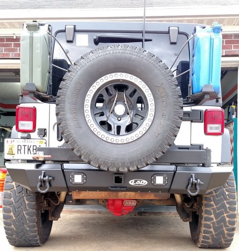
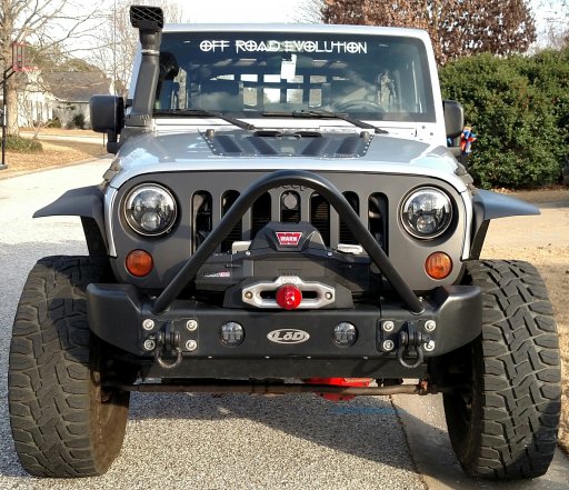
My working list for 2015 JKUR Electrical Power Distribution
BS= Blue Sea
All wire is marine grade tinned, copper strand
Battery Direct Power:
-ARB dual compressor (two 30 amp maxi fuses inline below breakers)
-ARB refrigerator (15 amp fuse inline below breakers) 8 gauge wire
-Susquehanna relay/flicker headlight control box ( fuse inline)
-sPod power distribution (50 amp inline resetting circuit breaker, 8 gauge wire)
-Driver side ignition triggered solenoid switched power (BS 12 fuse block, 8 gauge wire with 80 amp? inline resetting circuit breaker)
-Passenger side ignition triggered, solenoid switched BS 8 fuse block (unfused power from Driver Side BS 12 fuse block via 8 gauge wire)
-Passenger side constant power (BS 6 fuse block via 60 amp circuit breaker)
[8 gauge positive; 6 gauge negative wires to battery run through the large firewall pass thru on the passenger side that comes out just below the battery tray. Requires removing the batteries, etc. to access the pass thru from the engine compartment side. 6 gauge negative ends below dash at 1 in/3 out distribution brick with 8 gauge ground wires continuing to passenger constant and passenger switched blocks and driver rear RIGrunner]
-Engine compartment constant power distribution (BS 4 fuse block)
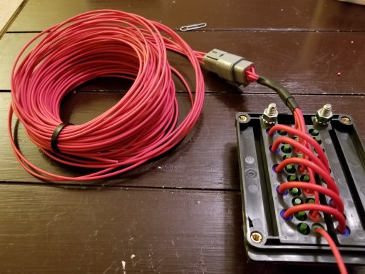
-Rear power distribution box, constant & relay switched (via 50 amp circuit breaker)
-Ham Radio power distribution [Powerwerx ITS - 12 timer/voltage disconnect module / Rigrunner 4005h 1 in, 5 out fused PowerPole connectors via unfused 8 gauge positive line from passenger BS 6 fuse block and 8 gauge line to grounding brick].
-Winch (Warn circuit breaker)
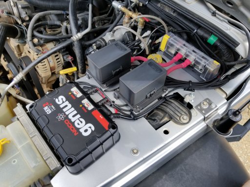
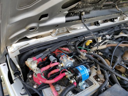
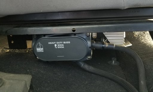
High-amp accessories like the winch go to the large center studs on the Genesis power and ground bus bars. When the batteries are connected, this will use the combined capacity of both batteries, spreading the load of the winch across both batteries. Once the cranking battery drops below 12.7v for 1 minute, all of the accessories that are connected to the power and ground buss bars will run from the aux battery only. This protects the cranking battery from being drained by the accessories. The batteries will remain isolated until the cranking battery is back up above 13.2v for 2 minutes, then they will automatically be reconnected. The G Screen monitor can display the voltage of each battery and whether they are connected or isolated. [Shane, Genesis Offroad July 13, 2017]
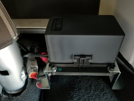
Cole Hersee 48530 series smart isolator between the two Optima Yellow top batteries
External Auxiliary Lights:
sPod (constant power through individual sPod 40 amp relays with individual Carling switch triggers in interior roof switch panel)
-Rock lights (combined red & white)
-Driving lights (dual pillar mounted Rigid D2s)
-Left Alley light (pillar mounted Rigid Dually)
-Right Alley light (pillar mounted Rigid Dually)
-Dual Rear Lights (Rigid SQs)
-Adjustable rear light (TS)
-Left Push Button (integrated power) on/off for sPod switch illumination
-Right Push Button with red indicator light(relay trigger for future rear fog or roof lights)
Driver Side Accessories Power Distribution:
Ignition Triggered Solenoid Switched Power Distribution (BS 12 Fuse Block)
Left Bank
-Radar Detector power
-Pillar Gauges illumination lights (via dimmer module)
-Pillar Gauges Power (oil temperature & oil pressure gauges)
-Driver side Maglite Charger
-DS map light(formerly Aeroforce Gauge aux power)
-Trigger for future roof light relay
Right Bank
-Switch Illumination Power (via switch in lower switch panel )
-CB radio relay trigger wire (via switch in lower switch panel)
-Dual USB Power Outlet (in lower switch panel)
-Glove Box Power (via switch in lower switch panel)
-Air compressor relay front trigger (via switch in lower switch panel)
-Anker USB Charger for upper dash USB dual head power cord & red USB cable
Unfused
-Jumper (red 8 gauge) positive to passenger side BS straight 8 fuse block
-Jumper (black 8 gauge) ground to passenger side BS straight 8 fuse block [unused]
Passenger Side Accessories Power Distribution:
Constant Power Distribution (BS 6 Fuse block)
Left Bank
-Map light (via passenger A pillar switch)
-Pillar (B pillar / sound bar) lights (via passenger A pillar switch)
-Glove box lights (via passenger A pillar switch)
Right Bank
-Floor light white (via passenger A pillar double throw switch)
-Floor lighting red LED strips (via A pillar double throw switch & remote control)
-(ARB Fridge or future roof lights relay?)
Unfused
-8 gauge + & - wire to Ham mobile radio power distribution (Powerwerx ITS - 12 / RIGrunner 4005h)
Ignition Switched Power Distribution (BS straight 8 fuse block)
-Trigger line to switched power relay in and for Rear PD Box
-Passenger Maglight charger
-ARB fridge monitor power
-Rear Camera(s) Monitor
-spare (possible future front camera?)
-spare (trigger wire for future rear fog lights relay?).
-spare (power wire for future rear fog lights relay?)
-spare (possible ARB compressor relay rear trigger power wire through rear roll bar panel switch ?)
CANBUS Ignition Switched Power (tapped from lighter/power port)
-spare
-spare
Engine Compartment Power Distribution:
Constant Power Distribution (driver side BS straight 4 fuse block)
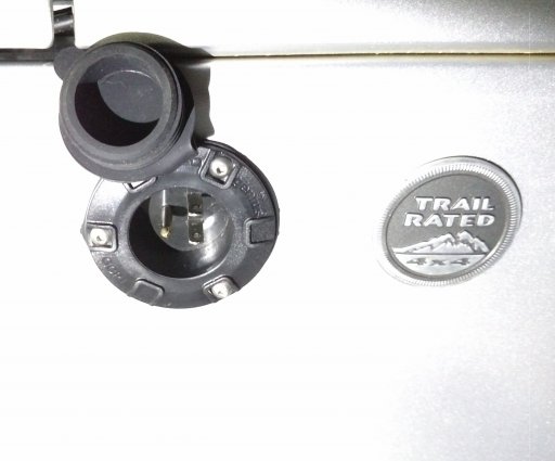
-Engine Compartment 12v Power Outlet
-Under hood Cyclone lights power (via push button switch)
-Red Rock Lights power (puddle mode)& winch lights relay trigger
-Winch lights power (relay triggered via push button bumper switch)
Rear Power Distribution Box :
Constant Power (through rear roll bar switch panel & straight 8 fuse block)
-Rear Roll Bar Switches Illumination (via roll bar panel switch)
-Cargo lights (via roll bar panel switch)
-Hatch lights (via roll bar panel switch)
-Tailgate lights (via roll bar panel switch)
-Water pump (relay trigger via roll bar panel switch)
-Rear switch for ARB compressor relay trigger
-Dual USB Outlet (via roll bar panel push button switch)
Constant Power (BS barrier strip in Rear Power Distribution Box)
-Dual 12 volt outlet
-Line to rear roll bar switch panel/BS 8 fuse block
-Water Pump (via in-box relay controlled with roll bar panel switched trigger)
-Power line to Ignition Switched Power Relay (in-box) feeding BS 4 fuse block
-(dual Powerpole outlet ?) (in parallel with dual 12 volt outlet)
-(power for rear switch to activate air compressor relay?)
Ignition Switched Power (BS 4 fuse block, controlled by in-box relay triggered from front passenger side BS 8 fuse block)
-Rear Camera power (red wire)
-( spare, 2nd rear camera power?)
-( spare, weatherpack?)
-( spare )
Radio Power Distribution (RIGrunner 4005H Powerpole connection box):
Constant Power (8 gauge + & - wires from passenger BS 6 fuse block) via Powerwerx ITS-12 Timer/Voltage Disconnect Switch Box (+ output post direct to RIGrunner, - output post to RIGrunner via inline fuse)
-Yaesu 400 XDR transceiver
-Powerwerx DB-750X transceiver
-(Cobra 75 CB radio relay power)
-Powerwerx Voltmeter/Temperature Meter monitor)
-(spare fan?)
[ITS-12 override switch with power from ITS-12 + input post]
Rear Power Switch Panel
0. Switch Lights
1. Cargo lights
2. Hatch lights
3. Tailgate lights
4. Air Compressor (relay trigger )
5. Water (relay trigger)
6. USB power outlet
7. USB Outlet Switch
Sent from my iPad using
OB Talk
