

Member III
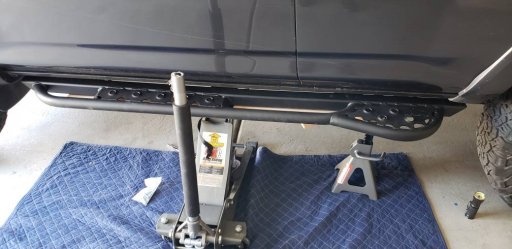
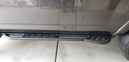
So I got my rock sliders in and here's how easy it was to install.
Member III
Member III
Well I wish it were a snap but it wasn't hard at all. Simply lift in place, align holes, unhook one clamp, start from one end and screw bolts in half way, check alignment, screw bolts tight then end by using torque wrench at 35 foot pounds to finish tightening.So I got my rock sliders in and here's how easy it was to install.

Member III
Member III


Contributor III

Enthusiast III
Member III
 and add the black edge guard to the cut edge.
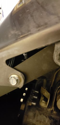

Expedition Master II
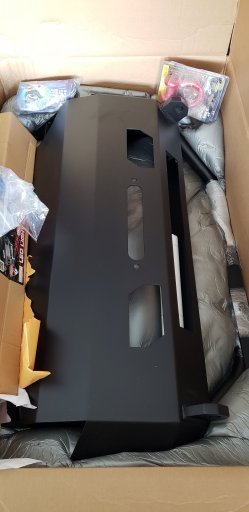
A very tidy and good lookin' package! Like the play by play instructions as well. Best of luck with the wiring. I spent yesterday working on the install of my Icom 5100A ham radio and antenna.Part One - Bumper Install … the heavy lifting
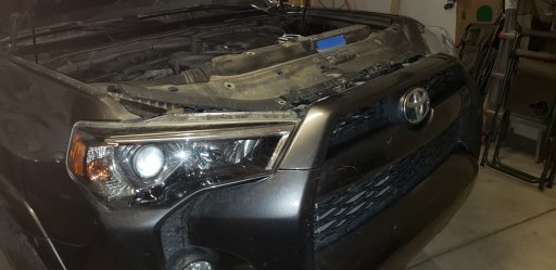
So the winch came in and it was that time to tackle the Bumper, Winch, and Light Bar install. First up...Lay out all the parts and make sure everything is at the ready--Check! Read the directions for the umpteenth time--Check! Rewatch all manufacturer recommended install videos again--Check! Call a friend and have him/her at the ready to help lift bumper and double check processes and assembly--Check!
View attachment 73529
Next--Get started. Take off the plastic front Bumper making sure to bag and mark the clips and bolts from each area separately. ie..Radiator cover top plate, under bumper, wheel wells, etc. (notice the plastic bag stuck on the radiator cover) I stuck all the clip/bolt bags to the radiator cover for safe keeping.
View attachment 73530
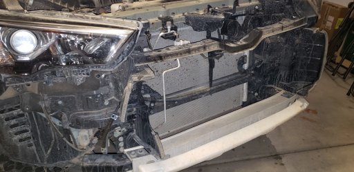
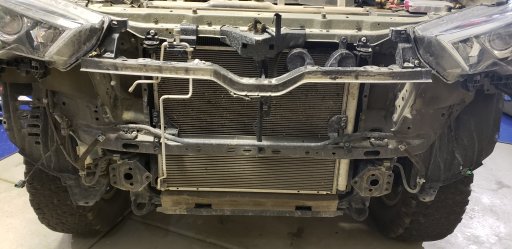
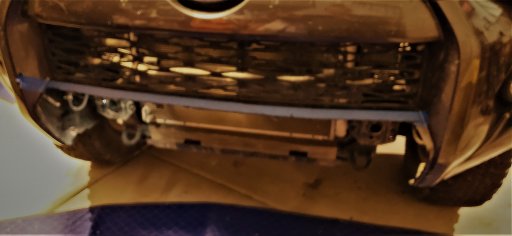
Once all fasteners were removed, I detached the plastic bumper from the non-removable clips and unhooked the fog lights. Then, carefully lifted the bumper off and placed it on a moving blanket so not to scratch it any more than it was. The plastic bumper removal exposed the metal bumper underneath which also needed removing.
View attachment 73532 View attachment 73533
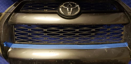
At this point my friend came by. While he assembled the winch and light bar for attachment to the bumper, I laid out the cut line on the plastic bumper according to the provided template. With Dremel in hand I finished the cut and removed the lower middle 'bulge' area. This is area the new bumper replaces. I also learned as I was cutting that plastic melts when using a high speed cutter and one should not pull the slag off the cut edge until it cools....it causes blisters. LOL
View attachment 73534
Next step -- reattach the plastic bumper View attachment 73535 and add the black edge guard to the cut edge.
Now for the heavy lifting. To ensure a not so aching back, it's good to have two people lift the metal bumper in place. (did I mention the heavy bumper is now heavier now that the winch and light bar is attached to it. Ouch! Well it was fairly strait forward to gently place the bumper into place. SSO welded on tabs that allow the bumper to hang in place while you bolt it on. Nice!
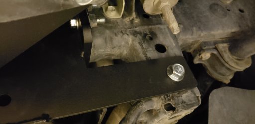
There were 10 bolts in total to attach the bumper snugly to the steal frame. Once they were properly torqued I moved on to attaching the flanges on the steal bumper so the plastic bumper could be properly fastened back.
View attachment 73536 View attachment 73537
That was it for the heavy lifting, now onto part two and wiring up the winch and lights.
View attachment 73538
Member III
Thanks.... now onto Part TwoA very tidy and good lookin' package! Like the play by play instructions as well. Best of luck with the wiring. I spent yesterday working on the install of my Icom 5100A ham radio and antenna.
And that melted plastic really sucks because it can stick to your skin while you jump around looking for a rag....
Looking forward to seeing the finished project!
Member III
Expedition Master II
I nice tidy job with a successful smoke test! Looks so clean it's almost a shame to take it out and get it dirty (not). Congrats! You should post a picture of the new front bumper and one of the new sliders in the same shot.Part Two -- Wiring up power to the Winch and Light
To avoid another mishap I experience once when installing a fuse box in the rear of the 4Runner where my wrench touched both terminals and pop...I had to replace a 50 amp fuse that was on the positive terminal. So this time, I started by putting rubber gloves over both terminals.
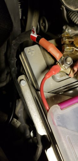
The winch was an easy hook up. Just fasten the red wire to the positive terminal on the battery and the black wire to side where the rest of the ground wires are bolted.
View attachment 73622
Now that that's done, onto the Heise Light hook up. This was a bit more work.
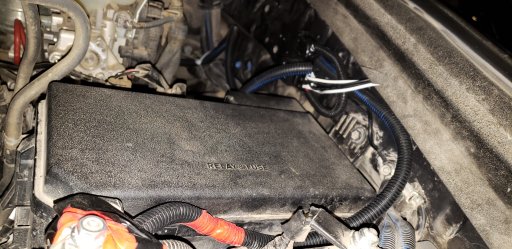
First off was mounting the Relay to the extra 10mm hole just beyond the humongous fuse box--easy peasy. Now I had to fasten the fuse above the Relay. This was accomplished with industrial hook & loop (Velcro). Then ran the power cable back to the positive terminal which I carefully tucked between the battery and fuse box.
View attachment 73623 View attachment 73624
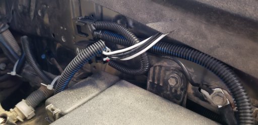
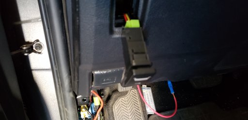
Now for the tucking away of the load lines. The EPauto harness that I purchased has two runs for two different load hook ups. I only needed one, but now have a spare tucked away for future use.
I ran both lines back to the bumper via the plastic guard. This allowed protection and an easy route back to the bumper.
View attachment 73625
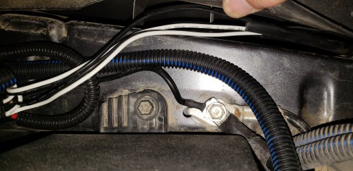
Now to the part that I was leaving purposely to the end of the install -- the switch install and poking through the firewall rubber grommet. Lucky for me I had recently bought supplies for a Tire Repair Clinic and I had an awl in the kit. With an easy poke through the grommet, I fished the single white relay wire run into the drivers side near the fuse box I needed to tap into.
My switch was designed for the Toyota panel so I popped out the lowest spare blank to avoid having to remove the panel under the steering wheel. Prior to this a soldered some extension wires to the switch wires so I could easily work with threading them through the rats nest of wires.
View attachment 73626
Thinking I was at the home stretch, I crimped the green switch wire to the White relay wire, the black to bolt on side metal for ground, and curled up and tucked away the yellow wire since I didn't really care to have it hooked up for dimming.
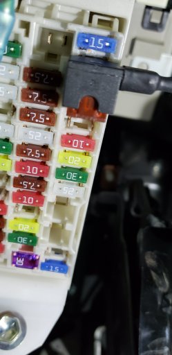
Now for the last wire (the red one) that goes to the fuse box. I decided not to do the old college way of wrapping the wire around a fuse leg and shoving it back in the fuse box. Much less, the low profile fuses do not allow for any wrapping. So I stopped what I was doing and ran to the auto store and bought a Bussmann Fuse Tap--What a wonderful invention. Got back home and tapped into a fuse that only works with the ignition on (personal choice).
View attachment 73627 View attachment 73628
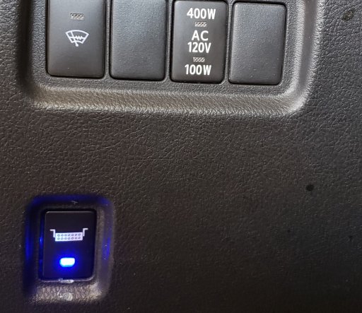
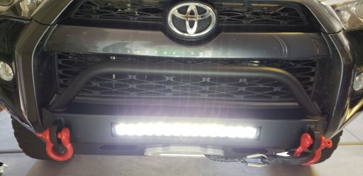
Once I plugged in the load line to the light bar and tested the switch,
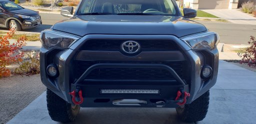
I snapped in the switch, buttoned up the area and took a proof positive picture that it's working.
View attachment 73629
This add on is officially done.
Member III
Thanks. It's looks clean because you can't see the rest of the Rig. I cleaned it twice before I started the install and it still had Trona Pinnacles mud spots on it. LOLI nice tidy job with a successful smoke test! Looks so clean it's almost a shame to take it out and get it dirty (not). Congrats! You should post a picture of the new front bumper and one of the new sliders in the same shot.

Pathfinder I
Member III
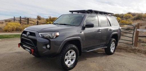
So Connie and I cleaned the rig known as 'Major Tom' and took it for a ride to dry it off. I must say that Trona Pinnacles mud is a pain to remove.I nice tidy job with a successful smoke test! Looks so clean it's almost a shame to take it out and get it dirty (not). Congrats! You should post a picture of the new front bumper and one of the new sliders in the same shot.
Expedition Master II
Well ground control thinks Major Tom looks great! How long had that Trona mud been on?So Connie and I cleaned the rig known as 'Major Tom' and took it for a ride to dry it off. I must say that Trona Pinnacles mud is a pain to remove.
View attachment 74035
Member III
Well ground control thinks Major Tom looks great! How long had that Trona mud been on?
3 weeks.
Member III
Pathfinder I
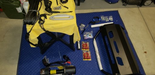
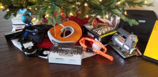
Jackpot!So my family and friends spoiled me this holiday season with new gear. I guess they want me to be safe and prepared on the trails. Now to find place for it all in the rig.
]
Expedition Master II
Congratulations! But I agree, 2 bags for recovery gear, air compressor, 1st aid (I use a day pack - carry a lot of stuff), and a tool kit that's about 25% of my space by volume! I think I need to move some of the recovery gear up to the rack, but that slows down packing. Especially if I need to break out the Raingler netting. It works great but takes time to use.So my family and friends spoiled me this holiday season with new gear. I guess they want me to be safe and prepared on the trails. Now to find place for it all in the rig.
View attachment 81257